For TCN-CSC-10C(V22), TCN-D900-9C(V22), TCN-CEL-10C(V22) and the paired TCN-CSC-10C(V22) with TCN-CSC-10N. First select single or paired vending machines, then the substrate.
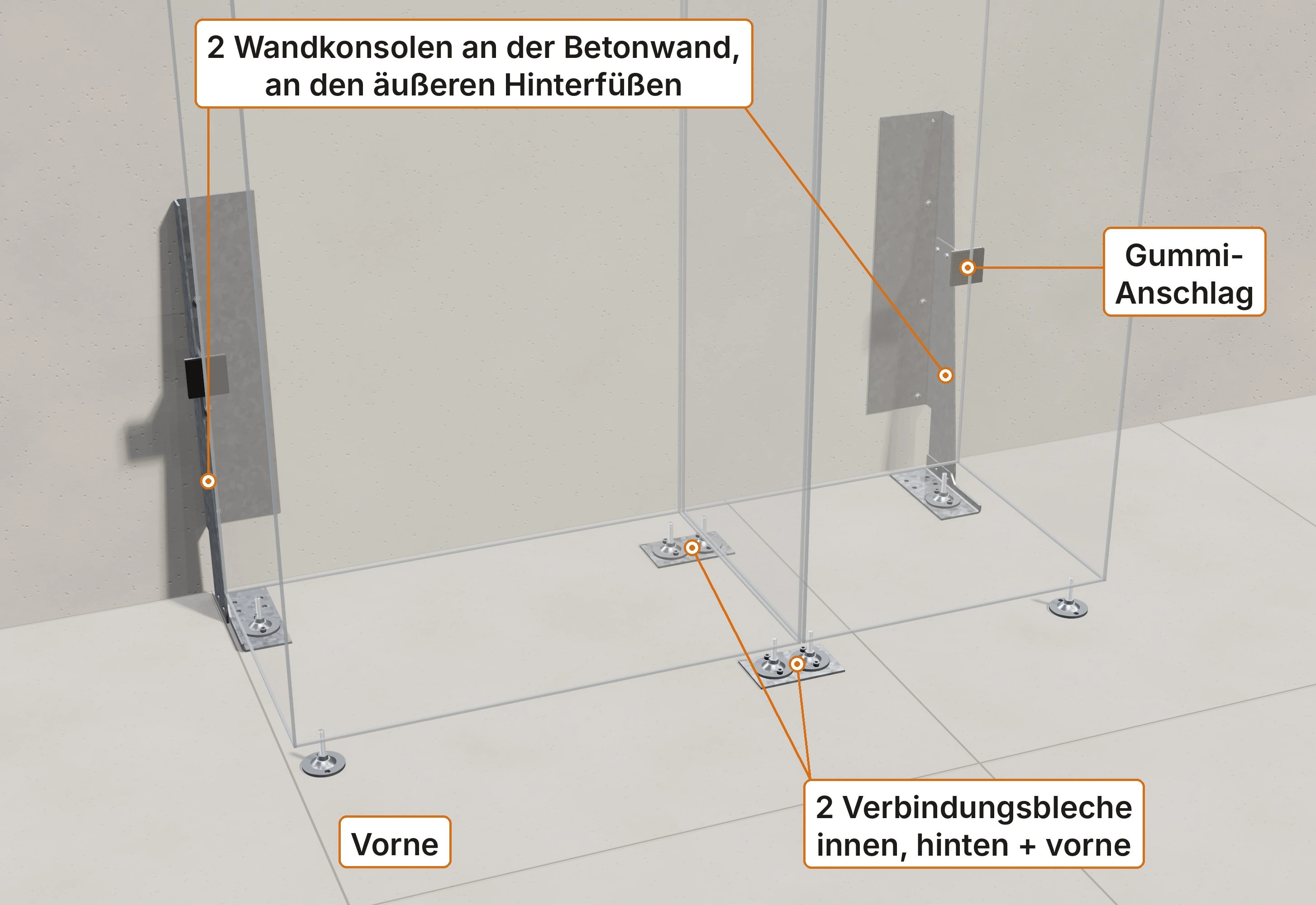
Secure the machines to the concrete wall: 2 brackets at the outer rear feet, 2 connecting plates under the inner feet at the rear and front.
WARNING – Risk of death from tipping. An unsecured or incorrectly secured vending machine can tip over and cause fatal injuries. Keep the mains plug disconnected during installation. Only put into operation after installation is complete and the checks have been passed. Do not drill where there is underfloor heating. Do not drill or screw into the cabinet.
Installation: 2 people, 2 pallet trucks. Installation only by personnel competent in this type of mechanical installation.
Wall kit on paired vending machines: two rear brackets and connecting plates at the front and rear · Large view
2 Wandkonsolen an der Betonwand, an den äußeren Hinterfüßen
2 wall brackets on the concrete wall, at the outer rear feet
Gummi-Anschlag
Rubber stop
2 Verbindungsbleche innen, hinten + vorne
2 connecting plates under the inner feet, rear + front
Vorne
Front
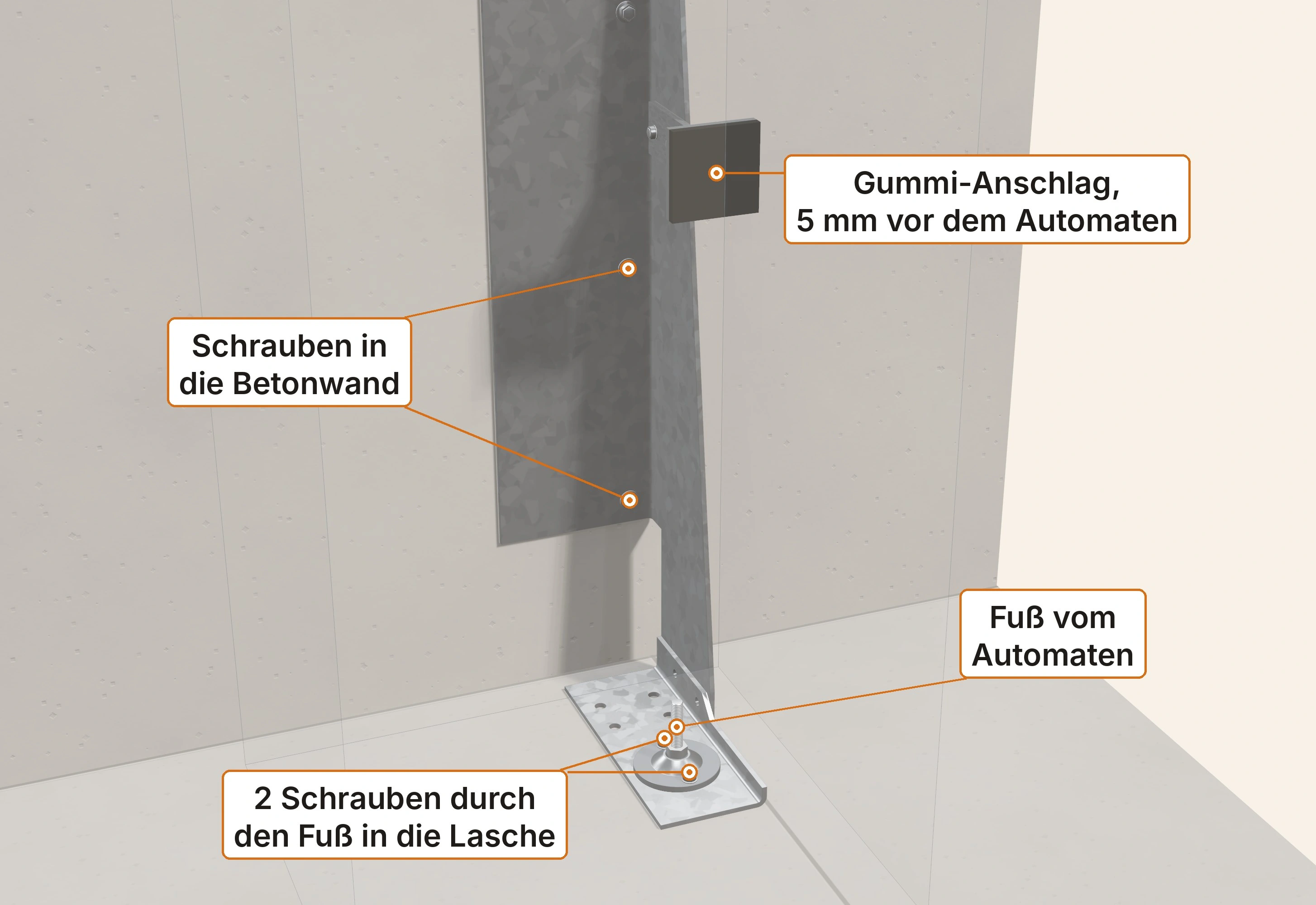
Detail of wall bracket with rubber stop and foot fastening · Large view
Gummi-Anschlag, 5 mm vor dem Automaten
Rubber stop, 5 mm from the machine
Schrauben in die Betonwand
Screws into the concrete wall
Fuß vom Automaten
Machine foot
2 Schrauben durch den Fuß in die Lasche
2 screws through the foot into the tab
Suitable for
Concrete wall at least 14 cm thick directly behind the machines. Identification: service detector shows a metal grid (reinforcement), very hard to drill, grey dust with grains of sand.
Not suitable for
Brick, calcium silicate block, aerated concrete, lightweight concrete block, stud wall, plasterboard in front of masonry, uncertain wall construction → floor instructions. Plasterboard in front of concrete → separate instructions.
Component overview
A = upright wall bracket; B = bracket under the foot; E = rubber stop on the wall bracket assembly.
C = connecting plate between the two machines, under the inner feet at the front and rear.
Flange = upturned edge of B; slotted hole = elongated slot for adjustment; foot circle = circular area on the bracket for the foot plate. Rib = stiffener on the wall bracket.
Terms
SW = spanner size in mm; Inbus = hex socket; Nm = unit of tightening torque.
M10×16 = metric M10 thread with a screw length of 16 mm; 8.8 = screw strength class.
ISO 7092 = washer standard; ISO 4762 = hex socket head cap screw standard.
fischer FBS II = specified concrete screw range; Loctite 243 = blue threadlocker.
ISO 7040 = self-locking nut standard.
C20/25 = concrete strength class; the designation alone does not establish suitability at the site.
Parts
2 parts B (L + R) – under the outer rear feet
2 parts A (L + R) – on the wall
4 M10×30 screws, strength class 8.8, with nuts – 2 per bracket, connecting A to B (45 Nm)
2 rubber stops E (L + R), each with 2 M8×25 screws, strength class 8.8, and self-locking nuts (ISO 7040)
12 M10×16 socket head cap screws (ISO 4762, 8.8) – 2 per foot, for 6 feet
12 sleeves, 6 mm long (from 14×1.8 tube)
12 narrow ISO 7092 washers (Ø 18) – 1 under each head
Blue Loctite 243
2 identical connecting plates – under the inner feet at the front and rear
6 concrete screws 10×100 (fischer FBS II) – 3 per part A
Cable clips
1 warning label “Do not shake or tip – risk of death”
Installation record
Tools
Rotary hammer
Masonry drill bit 6 mm (test hole)
Masonry drill bit 10 mm (10×210)
Service detector, hole blow-out pump
Ratchet + socket SW 15/16/17, ring spanner SW 16/17
Torque wrench
Short angled hex key SW 8
Torch, mirror, spirit level
2 pallet trucks
Folding rule
Removal: angle grinder, filling knife
5 mm wooden gauge
Before you start
Before use, the foot hole spacing, sleeve fit and effective M10 thread engagement must be confirmed. Do not install if there is a mismatch.
Before assembly: unplug and completely empty the machines. Secure against tipping and unintended lowering throughout foot adjustment, lifting, positioning parts underneath and lowering. Do not reach under an unsecured load. If safe lifting and support are unavailable: stop assembly and engage a specialist contractor.
If unsure about the substrate, component fit or safe assembly: do not assemble; consult a specialist contractor.
Clearances: 30 cm at the sides, 2.5 m clear in front.
At the rear, keep the wall clear at the outer sides up to 1.10 m: no radiator or window sill.
Keep 20 cm of wall clear behind each bracket: no socket in the way.
Wall at least 14 cm thick. Anchors at least 10.5 cm from the end of the wall (no corner, doorway or recess).
Scan the wall with the service detector.
Before every test hole, check the drilling point with the service detector. Drill a 6 mm test hole at a height of 53 cm.
Use these instructions only if: service detector shows a metal grid (reinforcement) and drilling is very hard and the dust is grey with grains of sand → concrete.
Grey dust but easy to drill → lightweight concrete block (masonry): do not use these instructions; check the floor.
White or red dust, soft, hollow or uncertain → do not use these instructions; check the floor. If in doubt, consult a specialist contractor (concrete class at least C20/25).
Installation
Position the machines
Position both machines close together, 1 m in front of the wall.
Screw the feet in
Screw all feet in as far as possible. Before fitting B/C, check the feet and required installation height: M14, unmarked or without proof of strength, maximum exposed length 30 mm between foot plate and cabinet; only with verified 8.8 strength, maximum 90 mm. Do not use bent feet. Carry out any necessary replacement only before installation, using an approved procedure; otherwise stop installation.
Rotate the foot plates
Rotate the foot plates until the holes are aligned front to rear.
Lift the inner feet
Lift the inner feet 1.5 cm with the pallet truck.
Place the connecting plates underneath
Place 1 connecting plate at each end, front and rear, under the inner feet. Lower the machines.
Fasten the connecting plates
At each hole: insert a sleeve. Insert an M10×16 screw with 1 narrow washer (ISO 7092, Ø 18) and 1 drop of Loctite 243. Tighten by hand.
Check the screw ends underneath
If a foot screw protrudes below the plate or bracket, or cannot be tightened correctly: stop assembly. Do not shorten the screw. Request a suitable shorter screw with confirmed thread engagement from the supplier; resume assembly only after clarification.
Lift the rear feet
Lift the outer rear feet 1.5 cm with the pallet truck.
Place part B under the rear feet
Place part B underneath: L on the left, R on the right.
Loosely fit the foot screws
At each hole: sleeve, M10×16 screw with narrow washer and Loctite 243. Screw in loosely only.
Position part A
Loosely screw part A to the upstand of part B using 2× M10×30, strength class 8.8. Both sides.
Move up to the wall
Move the paired machines towards the wall until the tabs of part A touch it.
Mark the holes
Mark the holes and tab outlines on the wall. Both sides.
Mark the feet
Mark the foot positions on the floor.
Pull forwards
Pull the paired machines 1 m forwards.
Remove part A
Unscrew part A. Part B stays attached to the foot.
Check for services
Use the service detector before every hole. Pay particular attention at a height of 23 cm.
Align part A with the marks
Hold part A against the marks on the wall.
Drill
Before every hole, check the drilling point with the service detector. Drill 10 mm through the 3 holes, to a depth of 110 mm from the wall surface.
Blow out
Blow out the drilled holes.
Fasten part A
Use the ratchet to screw in 3 concrete screws 10×100 until the heads seat. Do not turn further.
Second side
Repeat steps 18 to 21 on the other side.
Move to 60 cm from the wall
Move the paired machines to 60 cm from the wall.
Route the cables
Keep the mains plug disconnected. Use clips to route the cables upwards on the wall or to the side. Leave nothing on the floor.
Lift and move back
Lift with the pallet truck (part B hangs from the foot). Move back until the upstand touches the rib.
Check cables, lower
Check with a torch and mirror: no cable under a foot or bracket. Then lower.
Unscrew the front feet
Unscrew the outer front feet by approx. 6 mm. This compensates for the 6 mm of steel under the other feet.
Level the machines
Adjust the feet until the spirit level on both machines reads level.
Measure the exposed thread again
After levelling, measure the exposed M14 spindle length between foot plate and cabinet again at every foot: unmarked or without proof of strength ≤ 30 mm; with verified 8.8 ≤ 90 mm. If exceeded, stop installation; remove the load and secure against tipping before making any correction.
Tighten foot screws by hand
Tighten all foot screws in part B from the side using the short hex key, hand-tight. No extension. If a foot screw protrudes below the plate or bracket, or cannot be tightened correctly: stop assembly. Do not shorten the screw. Request a suitable shorter screw with confirmed thread engagement from the supplier; resume assembly only after clarification.
Bolt the bracket together
Insert 2× M10×30, strength class 8.8, through the slot and upstand. Head on the inside, nut on the outside. 45 Nm. Both sides.
Attach the rubber stop
Attach rubber stop E to the rib with 2× M8×25, strength class 8.8 (slots at a height of 70 cm). Do not tighten yet. Both sides.
Adjust the rubber stop
Slide the rubber stop forwards to 5 mm from the rear panel (wooden gauge).
Tighten the rubber stop
Tighten M8 to 25 Nm. Both sides.
Checks
Pull firmly and shake at the top of both machines; also push backwards. Nothing may move or lift, at either the rear or front.
Apply a neutral warning label “Do not shake or tip – risk of death” at eye level.
Complete the record: date, location, kit, substrate / floor covering thickness, screw length, checks passed, name. Connect to power: only insert the mains plug after the kit is fully installed and checked; only then put into operation.
Removal
Disconnect the mains plug. Before releasing the kit, empty the machines completely and secure against tipping.
Loosen 2× M10×30 on each side.
Screw the outer front feet back in by approx. 6 mm.
Pull the paired machines 1 m forwards.
Unscrew 3 concrete screws from each part A. Remove part A.
Loosen the foot screws (blue Loctite: a short, sharp turn).
Lift the feet with the pallet truck. Remove the connecting plates and part B.
Fill the holes.
Important
Concrete wall only. Masonry, plasterboard in front of masonry, stud wall: floor instructions.
Never omit the rubber stop: it absorbs impacts from the front; without it the rear foot bends.
Dry indoor areas only.
Always connect at the front and rear. Do not omit any parts.
Do not drill or screw into the cabinet. The kit attaches only to the levelling feet.
Only blue Loctite (243), never red. Foot screws hand-tight only, short hex key, no extension.
Only narrow ISO 7092 washers (Ø 18). Wider washers foul the cone of the foot plate.
The skirting board stays in place (up to 19.5 cm high and 3.5 cm thick).
Rear panel 20.5 cm from the wall: ventilation needs 20 cm.
After an impact: inspect all foot spindles with a torch. If bent or crooked: switch off the machine and keep it out of service. Replace the foot only using an approved procedure; then repeat the full inspection for this case.
Check screw connections when restocking. Annually and after every relocation: visually inspect and repeat the full inspection above. Check and retighten each connection only as specified in its assembly instructions; foot screws remain hand-tight.
If the machines are relocated: empty them, release the kit, reinstall and check at the new location.
Paired vending machines – Wall: plasterboard in front of concrete
Secure the machines to the concrete wall behind plasterboard: concrete screws in steel tubes through the board and cavity.
WARNING – Risk of death from tipping. An unsecured or incorrectly secured vending machine can tip over and cause fatal injuries. Keep the mains plug disconnected during installation. Only put into operation after installation is complete and the checks have been passed. Do not drill where there is underfloor heating. Do not drill or screw into the cabinet.
Installation: 2 people, 2 pallet trucks. Installation only by personnel competent in this type of mechanical installation.
Wall kit on paired vending machines: two rear brackets and connecting plates at the front and rear · Large view
2 Wandkonsolen an der Betonwand, an den äußeren Hinterfüßen
2 wall brackets on the concrete wall, at the outer rear feet
Gummi-Anschlag
Rubber stop
2 Verbindungsbleche innen, hinten + vorne
2 connecting plates under the inner feet, rear + front
Vorne
Front
Detail of wall bracket with rubber stop and foot fastening · Large view
Gummi-Anschlag, 5 mm vor dem Automaten
Rubber stop, 5 mm from the machine
Schrauben in die Betonwand
Screws into the concrete wall
Fuß vom Automaten
Machine foot
2 Schrauben durch den Fuß in die Lasche
2 screws through the foot into the tab
Suitable for
Plasterboard in front of a concrete wall at least 14 cm thick. Board and cavity combined maximum 8 cm. Identification: board sounds hollow, hard concrete behind it.
Not suitable for
Board + cavity over 8 cm. Plasterboard in front of masonry, stud wall → floor instructions.
Component overview
A = upright wall bracket; B = bracket under the foot; E = rubber stop on the wall bracket assembly.
C = connecting plate between the two machines, under the inner feet at the front and rear.
Flange = upturned edge of B; slotted hole = elongated slot for adjustment; foot circle = circular area on the bracket for the foot plate. Rib = stiffener on the wall bracket.
Terms
SW = spanner size in mm; Inbus = hex socket; Nm = unit of tightening torque.
M10×16 = metric M10 thread with a screw length of 16 mm; 8.8 = screw strength class.
ISO 7092 = washer standard; ISO 4762 = hex socket head cap screw standard.
fischer FBS II = specified concrete screw range; Loctite 243 = blue threadlocker.
ISO 7040 = self-locking nut standard.
Tube 18×2 = 18 mm outside diameter and 2 mm wall thickness.
Parts
2 parts B (L + R) – under the outer rear feet
2 parts A (L + R) – on the wall
4 M10×30 screws, strength class 8.8, with nuts – 2 per bracket, connecting A to B (45 Nm)
2 rubber stops E (L + R), each with 2 M8×25 screws, strength class 8.8, and self-locking nuts (ISO 7040)
12 M10×16 socket head cap screws (ISO 4762, 8.8) – 2 per foot, for 6 feet
12 sleeves, 6 mm long (from 14×1.8 tube)
12 narrow ISO 7092 washers (Ø 18) – 1 under each head
Blue Loctite 243
2 identical connecting plates – under the inner feet at the front and rear
6 concrete screws (fischer FBS II) – 3 per part A. Length according to board + cavity: up to 4.9 cm 10×140 · up to 6.9 cm 10×160 · up to 8 cm 10×200
6 steel tubes 18×2 – length exactly equal to board + cavity (1 per concrete screw)
2 tubes Ø 20×2 – length exactly equal to board + cavity (1 per small hole at 107.5 cm)
2 wall plugs 8 + 2 screws 6×100 (6×140 if board + cavity exceeds 5 cm) – for the small hole
Cable clips
1 warning label “Do not shake or tip – risk of death”
Installation record
Tools
Rotary hammer
Masonry drill bit 6 mm (test hole)
Masonry drill bit 10 mm, long enough for screw length + 1 cm from the plasterboard surface (10×210 or 10×260)
Drill bits 20 mm and 22 mm for plasterboard
Masonry drill bit 8 mm (wall plug 8)
Service detector, hole blow-out pump
Ratchet + socket SW 15/16/17, ring spanner SW 16/17
Torque wrench
Short angled hex key SW 8
Saw + file (for spacer tubes only)
Torch, mirror, spirit level
2 pallet trucks
Folding rule
Removal: angle grinder, filling knife
5 mm wooden gauge
Before you start
Before use, the foot hole spacing, sleeve fit and effective M10 thread engagement must be confirmed. Do not install if there is a mismatch.
Before assembly: unplug and completely empty the machines. Secure against tipping and unintended lowering throughout foot adjustment, lifting, positioning parts underneath and lowering. Do not reach under an unsecured load. If safe lifting and support are unavailable: stop assembly and engage a specialist contractor.
If unsure about the substrate, component fit or safe assembly: do not assemble; consult a specialist contractor.
Clearances: 30 cm at the sides, 2.5 m clear in front.
At the rear, keep the wall clear at the outer sides up to 1.10 m: no radiator or window sill.
Keep 20 cm of wall clear behind each bracket: no socket in the way.
Wall at least 14 cm thick. Anchors at least 10.5 cm from the end of the wall (no corner, doorway or recess).
Scan the wall with the service detector.
Before every test hole, check the drilling point with the service detector. Drill a 6 mm test hole at a height of 53 cm.
Use these instructions only if: the board sounds hollow and there is concrete behind it (metal grid, very hard to drill, grey dust with grains of sand).
Measure board + cavity: maximum 8 cm. More → do not use these instructions; check the floor.
Masonry or stud wall behind the board → do not use these instructions; check the floor. If in doubt, consult a specialist contractor.
Installation
Position the machines
Position both machines close together, 1 m in front of the wall.
Screw the feet in
Screw all feet in as far as possible. Before fitting B/C, check the feet and required installation height: M14, unmarked or without proof of strength, maximum exposed length 30 mm between foot plate and cabinet; only with verified 8.8 strength, maximum 90 mm. Do not use bent feet. Carry out any necessary replacement only before installation, using an approved procedure; otherwise stop installation.
Rotate the foot plates
Rotate the foot plates until the holes are aligned front to rear.
Lift the inner feet
Lift the inner feet 1.5 cm with the pallet truck.
Place the connecting plates underneath
Place 1 connecting plate at each end, front and rear, under the inner feet. Lower the machines.
Fasten the connecting plates
At each hole: insert a sleeve. Insert an M10×16 screw with 1 narrow washer (ISO 7092, Ø 18) and 1 drop of Loctite 243. Tighten by hand.
Check the screw ends underneath
If a foot screw protrudes below the plate or bracket, or cannot be tightened correctly: stop assembly. Do not shorten the screw. Request a suitable shorter screw with confirmed thread engagement from the supplier; resume assembly only after clarification.
Lift the rear feet
Lift the outer rear feet 1.5 cm with the pallet truck.
Place part B under the rear feet
Place part B underneath: L on the left, R on the right.
Loosely fit the foot screws
At each hole: sleeve, M10×16 screw with narrow washer and Loctite 243. Screw in loosely only.
Position part A
Loosely screw part A to the upstand of part B using 2× M10×30, strength class 8.8. Both sides.
Move up to the wall
Move the paired machines towards the wall until the tabs of part A touch it.
Mark the holes
Mark the 3 holes, tab outline and small hole at 107.5 cm. Both sides.
Mark the feet
Mark the foot positions on the floor.
Pull forwards
Pull the paired machines 1 m forwards.
Remove part A
Unscrew part A. Part B stays attached to the foot.
Check for services
Use the service detector before every hole. Pay particular attention at a height of 23 cm.
Enlarge the plasterboard holes
Before every hole, check the drilling point with the service detector. Enlarge the 3 holes in the plasterboard to 20 mm.
Measure board + cavity
Measure board + cavity. Then select the screw: up to 4.9 cm 10×140 · up to 6.9 cm 10×160 · up to 8 cm 10×200.
Cut the tubes to length
Cut 18×2 tubes exactly to the length of board + cavity. File the cut edge.
Insert the tubes
Insert an 18×2 tube into each of the 3 holes.
Drill through the tube
Before every hole, check the drilling point with the service detector. Drill 10 mm through the tube. Depth from plasterboard surface = screw length + 1 cm (10×140 → 15 cm · 10×160 → 17 cm · 10×200 → 21 cm).
Blow out
Blow out the drilled holes.
Enlarge the small hole
Before every hole, check the drilling point with the service detector. Enlarge the small hole (107.5 cm) in the plasterboard to 22 mm.
Insert the Ø 20 tube
Cut the Ø 20×2 tube exactly to the length of board + cavity and insert it.
Position part A
Hold part A against the wall.
Fasten part A
Use the ratchet to insert 3 concrete screws (length from step 19) through the tubes until the heads seat. Do not turn further.
Fasten the small hole
Small hole: wall plug 8 and screw 6×100 (6×140 if board + cavity exceeds 5 cm).
Second side
Repeat steps 18 to 28 on the other side.
Move to 60 cm from the wall
Move the paired machines to 60 cm from the wall.
Route the cables
Keep the mains plug disconnected. Use clips to route the cables upwards on the wall or to the side. Leave nothing on the floor.
Lift and move back
Lift with the pallet truck (part B hangs from the foot). Move back until the upstand touches the rib.
Check cables, lower
Check with a torch and mirror: no cable under a foot or bracket. Then lower.
Unscrew the front feet
Unscrew the outer front feet by approx. 6 mm. This compensates for the 6 mm of steel under the other feet.
Level the machines
Adjust the feet until the spirit level on both machines reads level.
Measure the exposed thread again
After levelling, measure the exposed M14 spindle length between foot plate and cabinet again at every foot: unmarked or without proof of strength ≤ 30 mm; with verified 8.8 ≤ 90 mm. If exceeded, stop installation; remove the load and secure against tipping before making any correction.
Tighten foot screws by hand
Tighten all foot screws in part B from the side using the short hex key, hand-tight. No extension. If a foot screw protrudes below the plate or bracket, or cannot be tightened correctly: stop assembly. Do not shorten the screw. Request a suitable shorter screw with confirmed thread engagement from the supplier; resume assembly only after clarification.
Bolt the bracket together
Insert 2× M10×30, strength class 8.8, through the slot and upstand. Head on the inside, nut on the outside. 45 Nm. Both sides.
Attach the rubber stop
Attach rubber stop E to the rib with 2× M8×25, strength class 8.8 (slots at a height of 70 cm). Do not tighten yet. Both sides.
Adjust the rubber stop
Slide the rubber stop forwards to 5 mm from the rear panel (wooden gauge).
Tighten the rubber stop
Tighten M8 to 25 Nm. Both sides.
Checks
Pull firmly and shake at the top of both machines; also push backwards. Nothing may move or lift, at either the rear or front.
Apply a neutral warning label “Do not shake or tip – risk of death” at eye level.
Complete the record: date, location, kit, substrate / floor covering thickness, screw length, checks passed, name. Connect to power: only insert the mains plug after the kit is fully installed and checked; only then put into operation.
Removal
Disconnect the mains plug. Before releasing the kit, empty the machines completely and secure against tipping.
Loosen 2× M10×30 on each side.
Screw the outer front feet back in by approx. 6 mm.
Pull the paired machines 1 m forwards.
Separately loosen the upper retaining screw at the small hole. Then unscrew 3 concrete screws per part A and remove part A. Secure the tubes against falling.
Loosen the foot screws (blue Loctite: a short, sharp turn).
Lift the feet with the pallet truck. Remove the connecting plates and part B.
Fill the holes.
Important
Concrete wall only. Masonry, plasterboard in front of masonry, stud wall: floor instructions.
Each concrete screw in an 18×2 tube. Tube length exactly equal to board + cavity. Maximum 8 cm.
Never omit the rubber stop: it absorbs impacts from the front; without it the rear foot bends.
Dry indoor areas only.
Always connect at the front and rear. Do not omit any parts.
Do not drill or screw into the cabinet. The kit attaches only to the levelling feet.
Only blue Loctite (243), never red. Foot screws hand-tight only, short hex key, no extension.
Only narrow ISO 7092 washers (Ø 18). Wider washers foul the cone of the foot plate.
The skirting board stays in place (up to 19.5 cm high and 3.5 cm thick).
Rear panel 20.5 cm from the wall: ventilation needs 20 cm.
After an impact: inspect all foot spindles with a torch. If bent or crooked: switch off the machine and keep it out of service. Replace the foot only using an approved procedure; then repeat the full inspection for this case.
Check screw connections when restocking. Annually and after every relocation: visually inspect and repeat the full inspection above. Check and retighten each connection only as specified in its assembly instructions; foot screws remain hand-tight.
If the machines are relocated: empty them, release the kit, reinstall and check at the new location.
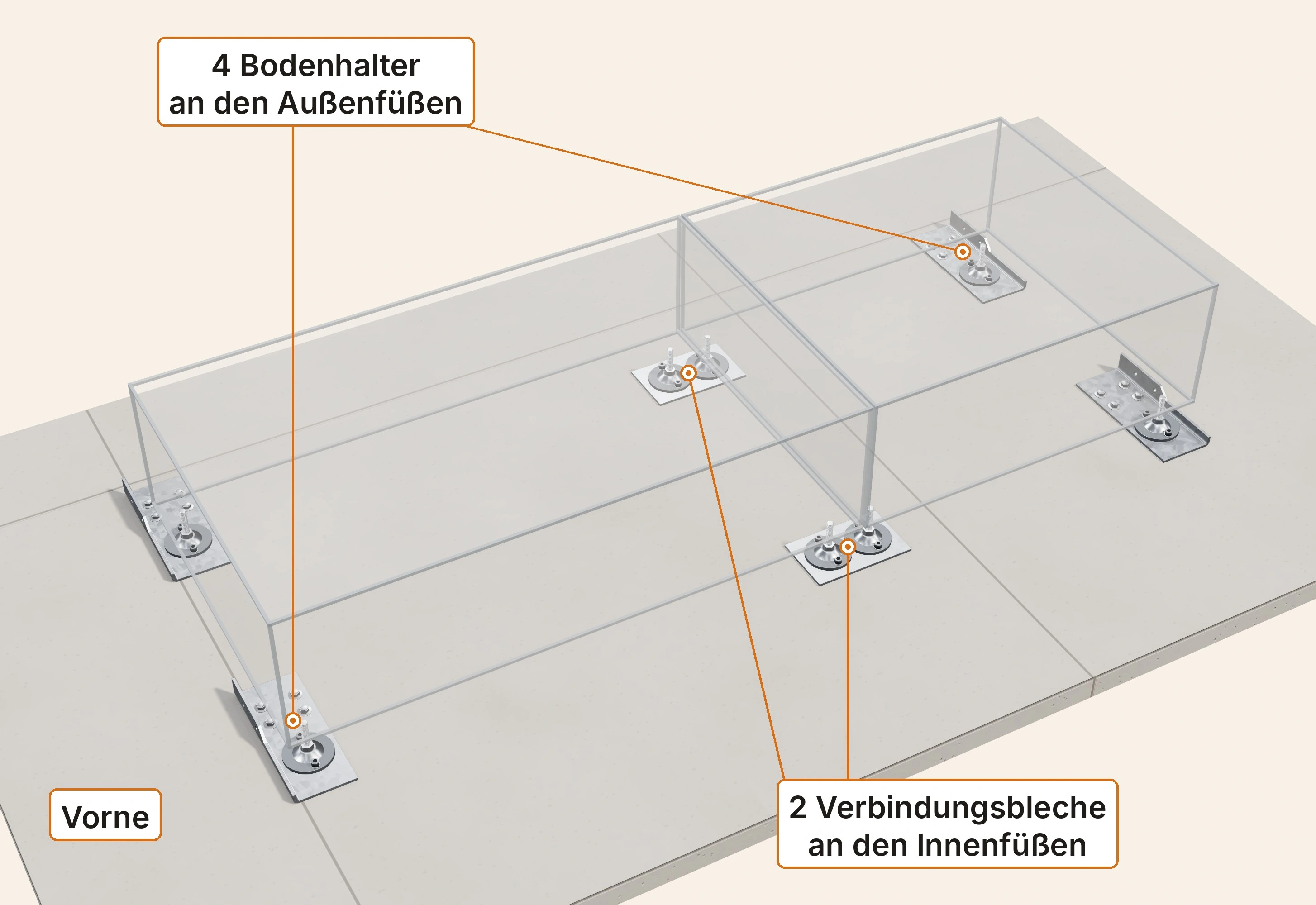
Secure the machines to the concrete floor: 4 parts B under the outer feet at the rear and front, 2 connecting plates under the inner feet. No part A.
WARNING – Risk of death from tipping. An unsecured or incorrectly secured vending machine can tip over and cause fatal injuries. Keep the mains plug disconnected during installation. Only put into operation after installation is complete and the checks have been passed. Do not drill where there is underfloor heating. Do not drill or screw into the cabinet.
Installation: 2 people, 2 pallet trucks. Installation only by personnel competent in this type of mechanical installation.
Floor kit on paired vending machines: four brackets under the outer feet and two connecting plates · Large view
4 Bodenhalter an den Außenfüßen
4 floor brackets at the outer feet
2 Verbindungsbleche an den Innenfüßen
2 connecting plates at the inner feet
Vorne
Front
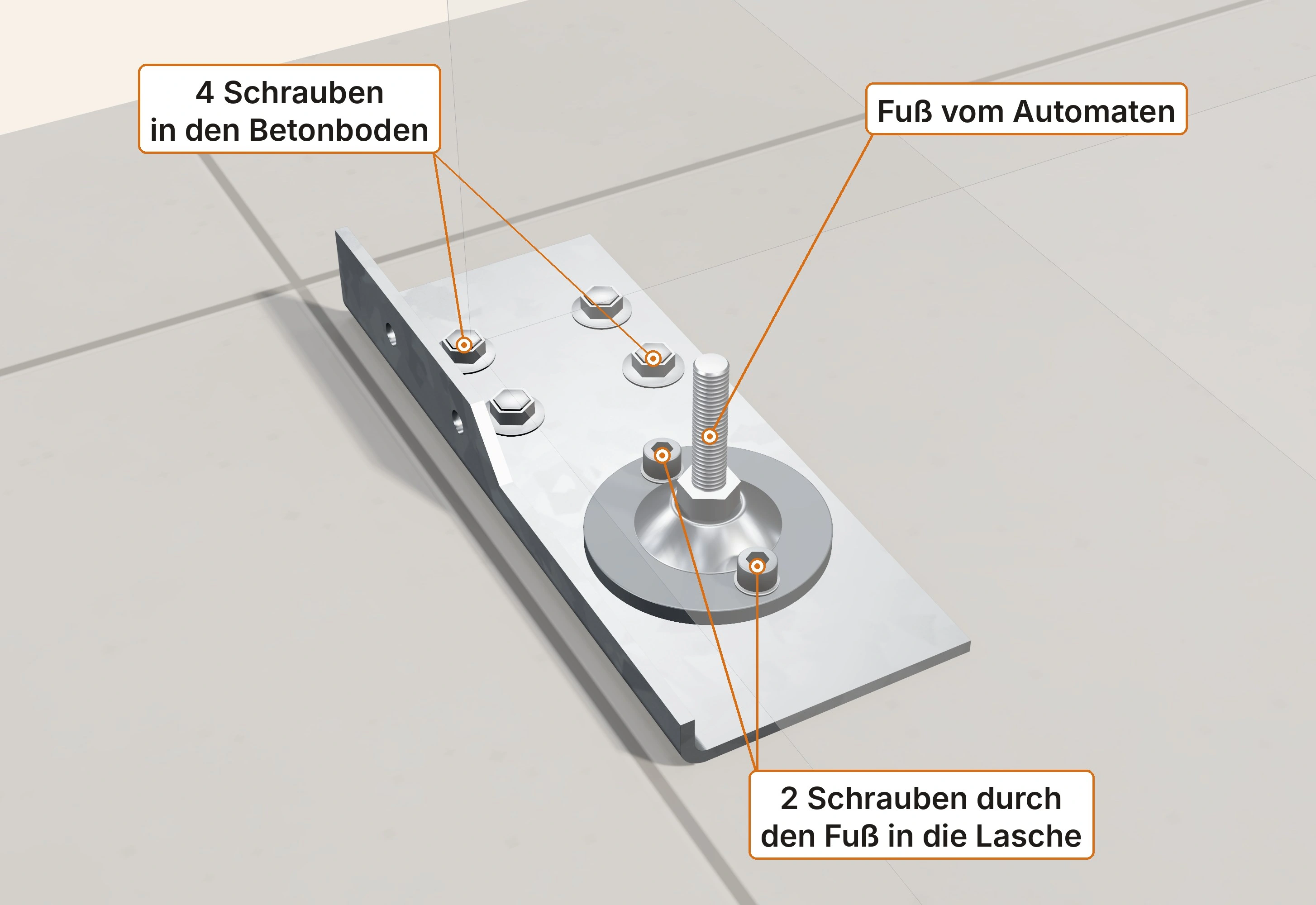
Floor bracket: four concrete screws and two screws at the foot · Large view
4 Schrauben in den Betonboden
4 screws into the concrete floor
Fuß vom Automaten
Machine foot
2 Schrauben durch den Fuß in die Lasche
2 screws through the foot into the tab
Suitable for
Concrete floor at least 14 cm thick, no steel fibres, no covering (maximum 0.9 cm). Identification: bare grey concrete.
Not suitable for
Steel-fibre concrete, underfloor heating (do not drill), raised access floor, timber floor, hollow-core slabs. Covering over 0.9 cm → “Floor: concrete with covering” instructions.
Component overview
B = bracket under the foot for floor fixing. A and E belong to the wall kit and are not included here.
C = connecting plate between the two machines, under the inner feet at the front and rear.
Flange = upturned edge of B; slotted hole = elongated slot for adjustment; foot circle = circular area on the bracket for the foot plate.
Terms
SW = spanner size in mm; Inbus = hex socket; Nm = unit of tightening torque.
M10×16 = metric M10 thread with a screw length of 16 mm; 8.8 = screw strength class.
ISO 7092 = washer standard; ISO 4762 = hex socket head cap screw standard.
fischer FBS II = specified concrete screw range; Loctite 243 = blue threadlocker.
Parts
4 parts B (2× L, 2× R) – under the outer rear feet and outer front feet
16 M10×16 socket head cap screws (ISO 4762, 8.8) – 2 per foot, for 8 feet
16 sleeves, 6 mm long (from 14×1.8 tube)
16 narrow ISO 7092 washers (Ø 18) – 1 under each head
Blue Loctite 243
2 identical connecting plates – under the inner feet at the front and rear
16 concrete screws 10×100 (fischer FBS II) – 4 per part B
Cable clips
1 warning label “Do not shake or tip – risk of death”
Installation record
Tools
Rotary hammer
Masonry drill bit 6 mm (test hole)
Masonry drill bit 10×260
Service detector, hole blow-out pump
Ratchet + socket SW 15/16/17, ring spanner SW 16/17
Torque wrench
Short angled hex key SW 8
Torch, mirror, spirit level
2 pallet trucks
Folding rule
Removal: angle grinder, filling knife
Before you start
Before use, the foot hole spacing, sleeve fit and effective M10 thread engagement must be confirmed. Do not install if there is a mismatch.
Before assembly: unplug and completely empty the machines. Secure against tipping and unintended lowering throughout foot adjustment, lifting, positioning parts underneath and lowering. Do not reach under an unsecured load. If safe lifting and support are unavailable: stop assembly and engage a specialist contractor.
If unsure about the substrate, component fit or safe assembly: do not assemble; consult a specialist contractor.
Only if wall mounting is not possible (no concrete wall, no plasterboard in front of concrete).
Clearances: 30 cm at the sides, 2.5 m clear in front.
A wall behind the machines: rear panel 20.5 cm from it. Freestanding → do not use these instructions.
Underfloor heating? Ask the landlord and look for the heating manifold. If there is underfloor heating, do not drill.
Raised access floor, timber floor, hollow-core slabs (drill bit drops through after a few cm) → do not use these instructions: check another position; frame only after technical approval.
Anchor centreline at least 10.5 cm from the edge of the concrete slab (no corner, doorway or recess).
Before every test hole, check the drilling point with the service detector. Test hole: concrete at least 14 cm thick, no steel fibres.
Identification: bare grey concrete, no covering (maximum 0.9 cm). Thicker covering → “Floor: concrete with covering” instructions.
Installation
Position the machines
Position both machines close together, 1 m in front of the wall.
Screw the feet in
Screw all feet in as far as possible. Before fitting B/C, check the feet and required installation height: M14, unmarked or without proof of strength, maximum exposed length 30 mm between foot plate and cabinet; only with verified 8.8 strength, maximum 90 mm. Do not use bent feet. Carry out any necessary replacement only before installation, using an approved procedure; otherwise stop installation.
Rotate the foot plates
Rotate the foot plates until the holes are aligned front to rear.
Lift the inner feet
Lift the inner feet 1.5 cm with the pallet truck.
Place the connecting plates underneath
Place 1 connecting plate at each end, front and rear, under the inner feet. Lower the machines.
Fasten the connecting plates
At each hole: insert a sleeve. Insert an M10×16 screw with 1 narrow washer (ISO 7092, Ø 18) and 1 drop of Loctite 243. Tighten by hand.
Check the screw ends underneath
If a foot screw protrudes below the plate or bracket, or cannot be tightened correctly: stop assembly. Do not shorten the screw. Request a suitable shorter screw with confirmed thread engagement from the supplier; resume assembly only after clarification.
Lift the rear feet
Lift the outer rear feet 1.5 cm with the pallet truck.
Place part B under the rear feet
Place part B underneath: L on the left, R on the right.
Loosely fit the foot screws
At each hole: sleeve, M10×16 screw with narrow washer and Loctite 243. Screw in loosely only.
Set the distance
Move the paired machines until the rear panel is 20.5 cm from the wall.
Mark the feet
Mark the foot positions on the floor.
Pull forwards
Pull the paired machines 1 m forwards.
Specify the screw
Covering maximum 0.9 cm: 10×100 screw, 10×260 drill bit, drilling depth 11 cm.
Position the front parts B
Place the 2 front parts B (L on the left, R on the right) on the outer front foot marks. Centre the foot hole pattern on the mark. Tab points backwards (towards the wall).
Mark the holes
Mark 4 holes per front tab (part B), 8 at the front. Remove both parts B.
Check for services
Use the service detector before every hole.
Drill
Before every hole, check the drilling point with the service detector. Drill 10 mm. Drill bit 10×260. Depth from top of floor = screw length + 1 cm = 11 cm.
Blow out
Blow out the drilled holes.
Fasten the front parts B
Position both parts B. Insert 4 concrete screws (10×100) per front tab until the heads seat. Do not turn further. 8 at the front, 8 at the rear, 16 concrete screws in total.
Move to 60 cm from the wall
Move the paired machines to 60 cm from the wall.
Route the cables
Keep the mains plug disconnected. Use clips to route the cables upwards on the wall or to the side. Leave nothing on the floor.
Lift and move back
Lift with the pallet truck (rear parts B hang from the feet). Move back to the foot marks (rear panel 20.5 cm from the wall).
Check cables, lower
Check with a torch and mirror: no cable under a foot or bracket. Then lower.
Check the feet
All feet rest on steel. The outer front feet rest on the front parts B, with the holes aligned.
Fasten the front feet
At each outer front foot hole: sleeve, M10×16 screw with narrow washer and Loctite 243. Screw in loosely.
Level the machines
Adjust the feet until the spirit level on both machines reads level.
Measure the exposed thread again
After levelling, measure the exposed M14 spindle length between foot plate and cabinet again at every foot: unmarked or without proof of strength ≤ 30 mm; with verified 8.8 ≤ 90 mm. If exceeded, stop installation; remove the load and secure against tipping before making any correction.
Tighten foot screws by hand
Tighten all foot screws in part B from the side using the short hex key, hand-tight. No extension. If a foot screw protrudes below the plate or bracket, or cannot be tightened correctly: stop assembly. Do not shorten the screw. Request a suitable shorter screw with confirmed thread engagement from the supplier; resume assembly only after clarification.
Rear: check for services
Use the service detector at the 4 holes in each rear part B (behind the machines).
Drill at the rear
Before every hole, check the drilling point with the service detector. Drill 10 mm through the 4 holes in each rear part B. Drill bit 10×260. Depth from top of floor = screw length + 1 cm = 11 cm.
Blow out the rear holes
Blow out the drilled holes.
Fasten the rear parts B
Use the ratchet to insert 4 concrete screws (10×100) per part B until the heads seat. Fit all 4; do not omit any.
Checks
Pull firmly and shake at the top of both machines; also push backwards. Nothing may move or lift, at either the rear or front.
Apply a neutral warning label “Do not shake or tip – risk of death” at eye level.
Complete the record: date, location, kit, substrate / floor covering thickness, screw length, checks passed, name. Connect to power: only insert the mains plug after the kit is fully installed and checked; only then put into operation.
Removal
Disconnect the mains plug. Before releasing the kit, empty the machines completely and secure against tipping.
Unscrew 4 concrete screws from each rear part B (behind the rear panel).
Loosen the foot screws at the outer front feet (blue Loctite: a short, sharp turn).
Pull the paired machines 1 m forwards.
Front parts B: unscrew 4 concrete screws from each.
Loosen the remaining foot screws (a short, sharp turn).
Lift the feet with the pallet truck. Remove the connecting plates and parts B.
Fill the holes.
Important
Do not drill where there is underfloor heating. For raised access or timber floors: frame only after technical approval; raised access floors only with a manufacturer's specification of at least 4 kN point load per panel.
Fit all 4 concrete screws per part B. Anchor centreline at least 10.5 cm from the edge.
The front parts B resist backward tipping: never omit them.
Dry indoor areas only.
Always connect at the front and rear. Do not omit any parts.
Do not drill or screw into the cabinet. The kit attaches only to the levelling feet.
Only blue Loctite (243), never red. Foot screws hand-tight only, short hex key, no extension.
Only narrow ISO 7092 washers (Ø 18). Wider washers foul the cone of the foot plate.
The skirting board stays in place (up to 19.5 cm high and 3.5 cm thick).
Rear panel 20.5 cm from the wall: ventilation needs 20 cm.
After an impact: inspect all foot spindles with a torch. If bent or crooked: switch off the machine and keep it out of service. Replace the foot only using an approved procedure; then repeat the full inspection for this case.
Check screw connections when restocking. Annually and after every relocation: visually inspect and repeat the full inspection above. Check and retighten each connection only as specified in its assembly instructions; foot screws remain hand-tight.
If the machines are relocated: empty them, release the kit, reinstall and check at the new location.
Paired vending machines – Floor: concrete with covering
Fasten the machines through tiles, screed or floating screed into the concrete beneath. Long concrete screws according to covering thickness.
WARNING – Risk of death from tipping. An unsecured or incorrectly secured vending machine can tip over and cause fatal injuries. Keep the mains plug disconnected during installation. Only put into operation after installation is complete and the checks have been passed. Do not drill where there is underfloor heating. Do not drill or screw into the cabinet.
Installation: 2 people, 2 pallet trucks. Installation only by personnel competent in this type of mechanical installation.
Floor kit on paired vending machines: four brackets under the outer feet and two connecting plates · Large view
4 Bodenhalter an den Außenfüßen
4 floor brackets at the outer feet
2 Verbindungsbleche an den Innenfüßen
2 connecting plates at the inner feet
Vorne
Front
Floor bracket: four concrete screws and two screws at the foot · Large view
4 Schrauben in den Betonboden
4 screws into the concrete floor
Fuß vom Automaten
Machine foot
2 Schrauben durch den Fuß in die Lasche
2 screws through the foot into the tab
Suitable for
Tiles/screed directly on concrete up to 6.5 cm (drill bit reaches hard concrete after a maximum of 6.5 cm). Floating screed up to 16 cm (soft insulation below the screed, then concrete). The load-bearing concrete beneath must be at least 14 cm thick.
Not suitable for
Covering over 16 cm. Tiles/screed directly on concrete over 6.5 cm. Underfloor heating (do not drill), raised access floor, timber floor, hollow-core slabs.
Component overview
B = bracket under the foot for floor fixing. A and E belong to the wall kit and are not included here.
C = connecting plate between the two machines, under the inner feet at the front and rear.
Flange = upturned edge of B; slotted hole = elongated slot for adjustment; foot circle = circular area on the bracket for the foot plate.
Terms
SW = spanner size in mm; Inbus = hex socket; Nm = unit of tightening torque.
M10×16 = metric M10 thread with a screw length of 16 mm; 8.8 = screw strength class.
ISO 7092 = washer standard; ISO 4762 = hex socket head cap screw standard.
fischer FBS II = specified concrete screw range; Loctite 243 = blue threadlocker.
Parts
4 parts B (2× L, 2× R) – under the outer rear feet and outer front feet
16 M10×16 socket head cap screws (ISO 4762, 8.8) – 2 per foot, for 8 feet
16 sleeves, 6 mm long (from 14×1.8 tube)
16 narrow ISO 7092 washers (Ø 18) – 1 under each head
Blue Loctite 243
2 identical connecting plates – under the inner feet at the front and rear
16 concrete screws (fischer FBS II) – 4 per part B. Length according to covering thickness, see table: up to 4.5 cm 10×140 · up to 6.5 cm 10×160 · up to 10 cm 10×200 · up to 13.5 cm 10×230 · up to 16 cm 10×260
Cable clips
1 warning label “Do not shake or tip – risk of death”
Installation record
Tools
Rotary hammer
Masonry drill bit 6 mm (test hole)
Masonry drill bits 10×260 (up to screw 10×160) and 10×460 (from screw 10×200)
Service detector, hole blow-out pump
Ratchet + socket SW 15/16/17, ring spanner SW 16/17
Torque wrench
Short angled hex key SW 8
Torch, mirror, spirit level
2 pallet trucks
Folding rule
Removal: angle grinder, filling knife
Before you start
Before use, the foot hole spacing, sleeve fit and effective M10 thread engagement must be confirmed. Do not install if there is a mismatch.
Before assembly: unplug and completely empty the machines. Secure against tipping and unintended lowering throughout foot adjustment, lifting, positioning parts underneath and lowering. Do not reach under an unsecured load. If safe lifting and support are unavailable: stop assembly and engage a specialist contractor.
If unsure about the substrate, component fit or safe assembly: do not assemble; consult a specialist contractor.
Only if wall mounting is not possible (no concrete wall, no plasterboard in front of concrete).
Clearances: 30 cm at the sides, 2.5 m clear in front.
A wall behind the machines: rear panel 20.5 cm from it. Freestanding → do not use these instructions.
Underfloor heating? Ask the landlord and look for the heating manifold. If there is underfloor heating, do not drill.
Raised access floor, timber floor, hollow-core slabs (drill bit drops through after a few cm) → do not use these instructions: check another position; frame only after technical approval.
Anchor centreline at least 10.5 cm from the edge of the concrete slab (no corner, doorway or recess).
Before every test hole, check the drilling point with the service detector. Test hole: concrete beneath at least 14 cm thick.
Tiles/screed directly on concrete: suitable if the test hole reaches hard concrete after a maximum of 6.5 cm.
Floating screed (soft insulating layer, yellow or white crumbly dust): suitable if screed + insulation are no more than 16 cm thick, with concrete beneath.
Measure and record the covering thickness at the test hole.
Screw length according to floor build-up
Floor covering thickness
FBS II
Drilling depth from surface
Drill bit
Applies to
up to 4.5 cm
10×140
15 cm
10×260
Tiles/screed directly on concrete or floating
up to 6.5 cm
10×160
17 cm
10×260
Tiles/screed directly on concrete or floating
up to 10 cm
10×200
21 cm
10×460
floating screed only
up to 13.5 cm
10×230
24 cm
10×460
floating screed only
up to 16 cm
10×260
27 cm
10×460
floating screed only
Installation
Position the machines
Position both machines close together, 1 m in front of the wall.
Screw the feet in
Screw all feet in as far as possible. Before fitting B/C, check the feet and required installation height: M14, unmarked or without proof of strength, maximum exposed length 30 mm between foot plate and cabinet; only with verified 8.8 strength, maximum 90 mm. Do not use bent feet. Carry out any necessary replacement only before installation, using an approved procedure; otherwise stop installation.
Rotate the foot plates
Rotate the foot plates until the holes are aligned front to rear.
Lift the inner feet
Lift the inner feet 1.5 cm with the pallet truck.
Place the connecting plates underneath
Place 1 connecting plate at each end, front and rear, under the inner feet. Lower the machines.
Fasten the connecting plates
At each hole: insert a sleeve. Insert an M10×16 screw with 1 narrow washer (ISO 7092, Ø 18) and 1 drop of Loctite 243. Tighten by hand.
Check the screw ends underneath
If a foot screw protrudes below the plate or bracket, or cannot be tightened correctly: stop assembly. Do not shorten the screw. Request a suitable shorter screw with confirmed thread engagement from the supplier; resume assembly only after clarification.
Lift the rear feet
Lift the outer rear feet 1.5 cm with the pallet truck.
Place part B under the rear feet
Place part B underneath: L on the left, R on the right.
Loosely fit the foot screws
At each hole: sleeve, M10×16 screw with narrow washer and Loctite 243. Screw in loosely only.
Set the distance
Move the paired machines until the rear panel is 20.5 cm from the wall.
Mark the feet
Mark the foot positions on the floor.
Pull forwards
Pull the paired machines 1 m forwards.
Select the screw
Measure the covering thickness at the test hole. Take screw, drill bit and depth from the “Covering thickness → screw / drill bit” table above.
Position the front parts B
Place the 2 front parts B (L on the left, R on the right) on the outer front foot marks. Centre the foot hole pattern on the mark. Tab points backwards (towards the wall).
Mark the holes
Mark 4 holes per front tab (part B), 8 at the front. Remove both parts B.
Check for services
Use the service detector before every hole.
Drill
Before every hole, check the drilling point with the service detector. Drill 10 mm. Drill bit and depth from the table (step 14). Depth from top of floor = screw length + 1 cm.
Blow out
Blow out the drilled holes.
Fasten the front parts B
Position both parts B. Insert 4 concrete screws (from step 14) per front tab until the heads seat. Do not turn further. 8 at the front, 8 at the rear, 16 concrete screws in total.
Move to 60 cm from the wall
Move the paired machines to 60 cm from the wall.
Route the cables
Keep the mains plug disconnected. Use clips to route the cables upwards on the wall or to the side. Leave nothing on the floor.
Lift and move back
Lift with the pallet truck (rear parts B hang from the feet). Move back to the foot marks (rear panel 20.5 cm from the wall).
Check cables, lower
Check with a torch and mirror: no cable under a foot or bracket. Then lower.
Check the feet
All feet rest on steel. The outer front feet rest on the front parts B, with the holes aligned.
Fasten the front feet
At each outer front foot hole: sleeve, M10×16 screw with narrow washer and Loctite 243. Screw in loosely.
Level the machines
Adjust the feet until the spirit level on both machines reads level.
Measure the exposed thread again
After levelling, measure the exposed M14 spindle length between foot plate and cabinet again at every foot: unmarked or without proof of strength ≤ 30 mm; with verified 8.8 ≤ 90 mm. If exceeded, stop installation; remove the load and secure against tipping before making any correction.
Tighten foot screws by hand
Tighten all foot screws in part B from the side using the short hex key, hand-tight. No extension. If a foot screw protrudes below the plate or bracket, or cannot be tightened correctly: stop assembly. Do not shorten the screw. Request a suitable shorter screw with confirmed thread engagement from the supplier; resume assembly only after clarification.
Rear: check for services
Use the service detector at the 4 holes in each rear part B (behind the machines).
Drill at the rear
Before every hole, check the drilling point with the service detector. Drill 10 mm through the 4 holes in each rear part B. Drill bit and depth from the table (step 14). Depth from top of floor = screw length + 1 cm.
Blow out the rear holes
Blow out the drilled holes.
Fasten the rear parts B
Use the ratchet to insert 4 concrete screws (from step 14) per part B until the heads seat. Fit all 4; do not omit any.
Checks
Pull firmly and shake at the top of both machines; also push backwards. Nothing may move or lift, at either the rear or front.
Apply a neutral warning label “Do not shake or tip – risk of death” at eye level.
Complete the record: date, location, kit, substrate / floor covering thickness, screw length, checks passed, name. Connect to power: only insert the mains plug after the kit is fully installed and checked; only then put into operation.
Removal
Disconnect the mains plug. Before releasing the kit, empty the machines completely and secure against tipping.
Unscrew 4 concrete screws from each rear part B (behind the rear panel).
Loosen the foot screws at the outer front feet (blue Loctite: a short, sharp turn).
Pull the paired machines 1 m forwards.
Front parts B: unscrew 4 concrete screws from each.
Loosen the remaining foot screws (a short, sharp turn).
Lift the feet with the pallet truck. Remove the connecting plates and parts B.
Fill the holes.
Important
Do not drill where there is underfloor heating. For raised access or timber floors: frame only after technical approval; raised access floors only with a manufacturer's specification of at least 4 kN point load per panel.
Fit all 4 concrete screws per part B. Anchor centreline at least 10.5 cm from the edge.
The front parts B resist backward tipping: never omit them.
Dry indoor areas only.
Always connect at the front and rear. Do not omit any parts.
Do not drill or screw into the cabinet. The kit attaches only to the levelling feet.
Only blue Loctite (243), never red. Foot screws hand-tight only, short hex key, no extension.
Only narrow ISO 7092 washers (Ø 18). Wider washers foul the cone of the foot plate.
The skirting board stays in place (up to 19.5 cm high and 3.5 cm thick).
Rear panel 20.5 cm from the wall: ventilation needs 20 cm.
After an impact: inspect all foot spindles with a torch. If bent or crooked: switch off the machine and keep it out of service. Replace the foot only using an approved procedure; then repeat the full inspection for this case.
Check screw connections when restocking. Annually and after every relocation: visually inspect and repeat the full inspection above. Check and retighten each connection only as specified in its assembly instructions; foot screws remain hand-tight.
If the machines are relocated: empty them, release the kit, reinstall and check at the new location.
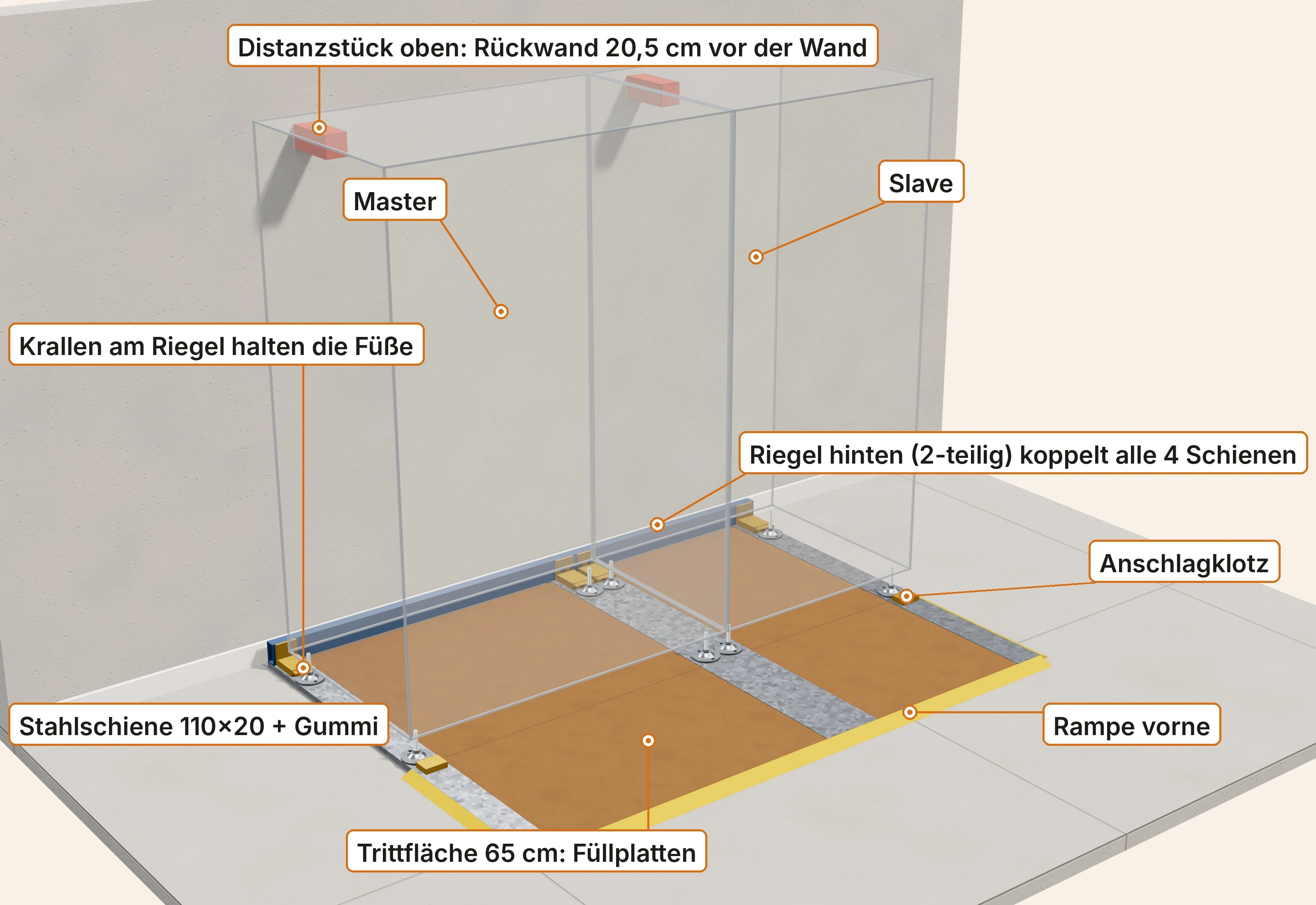
Use only after technical approval. The paired machines stand on 4 steel rails projecting 65 cm forwards, with crossbar, retaining claws and tread plates.
WARNING – Risk of death from tipping. An unsecured or incorrectly secured vending machine can tip over and cause fatal injuries. Keep the mains plug disconnected during installation. Only put into operation after installation is complete and the checks have been passed. Do not drill where there is underfloor heating. Do not drill or screw into the cabinet.
Installation: 4 people when placing and moving the machines, 2 pallet trucks. Installation only by personnel competent in this type of mechanical installation.
Pair of vending machines on four rails. At the rear, the crossbar connects all rails; four clamps hold the rear feet. Two stop blocks sit at the outer front positions, with a standing surface and ramp in front of the machines. Two pressure buffers are fixed high on the wall. · Large view
Distanzstück oben: Rückwand 20,5 cm vor der Wand
Upper spacer: rear panel 20.5 cm from the wall
Master
Master
Slave
Slave
Krallen am Riegel halten die Füße
Retaining claws on the crossbar hold the feet
Riegel hinten (2-teilig) koppelt alle 4 Schienen
Rear crossbar (2 sections) connects all 4 rails
Anschlagklotz
Stop block
Stahlschiene 110×20 + Gummi
Steel rail 110×20 + rubber
Rampe vorne
Front ramp
Trittfläche 65 cm: Füllplatten
65 cm tread surface: infill plates
Suitable for
Level, load-bearing floor and a wall capable of taking compression loads 20–30 cm behind the paired machines. Raised access floor only with a manufacturer's specification of at least 4 kN point load per panel.
Not suitable for
Less than 65 cm clear in front of the paired machines. Uneven floor (more than 3 mm over 1 m). Raised access floor without confirmed 4 kN point load per panel. No wall capable of taking compression loads 20–30 cm behind. Underfloor heating: do not drill and do not use the frame without separate technical approval.
Component overview
Rails support the feet; the rear crossbar connects the rails. Clamps hold the rear feet, and stop blocks sit at the outer front positions. Standing panels fill the gaps, with the ramp at the front. Pressure buffers sit high on the wall.
Terms
SW = spanner size in mm; Inbus = hex socket; Nm = unit of tightening torque.
Crossbar joint = connection between the two crossbar sections; crane scale = instrument for measuring tensile load.
Parts
4 steel rails S235 110×20 mm without stiffeners – one per row of feet
1 rear crossbar (rectangular tube 80×40), 1275 + 882 mm, with 2 side splice plates 60×6 mm and 4× M10 8.8 – must never be omitted
4 retaining claws – for the 4 rear feet
2 stop blocks – at the outer front positions
8 sliding strips – 1 per foot position
3 mm rubber strips – under the rails
15 mm tread plates / infill plates between the rails all the way to the rear, anti-slip tape or aluminium chequer plate at the front
25 mm rubber ramp – at the front
2 compression buffers (spacers) with 100×100 pressure plate and rubber – on the wall
5 mm wooden gauge
M10 screws: 4× M10 8.8 for the crossbar joint with 2 side splice plates 60×6 mm, 8 for crossbar to rails (2 per rail), 12 for retaining claws (3 each), 4 for stop blocks (2 each)
Shim plates (if needed, between retaining claw and crossbar)
1 warning label “Do not shake or tip – risk of death”, installation record
Tools
Crane scale for the site check with 150 kg tensile load.
Ratchet + socket SW 16/17, ring spanner SW 16/17
Torque wrench (45 Nm)
Angled hex keys SW 8, SW 6 and SW 4
Straightedge 1 m, spirit level, folding rule
2 pallet trucks (fork assembly maximum 600 mm wide; electric pallet trucks in creep mode only)
For compression buffers: adhesive or 2 screws suitable for the wall. Service detector for buffer fixing holes.
Camera / phone for photo acceptance
SW 22 spanner for the foot nut.
Before you start
Before assembly: unplug and completely empty the machines. Secure against tipping and unintended lowering throughout foot adjustment, lifting, positioning parts underneath and lowering. Do not reach under an unsecured load. If safe lifting and support are unavailable: stop assembly and engage a specialist contractor.
If unsure about the substrate, component fit or safe assembly: do not assemble; consult a specialist contractor.
Use frame only after technical approval. Foot fit, connections and load-bearing capacity must be confirmed.
Screw the foot fully in and measure the exposed length. Check the SW 22 nut.
Keep 65 cm clear in front of the machines.
Level floor: maximum deviation 3 mm over a 1 m straightedge.
Raised access floor: only with a manufacturer's specification of at least 4 kN point load per panel.
The machines stand 20–30 cm in front of a wall capable of taking compression loads (concrete, masonry or plasterboard on studs).
Pallet truck access from the front.
Are all parts in the package? All parts must be fitted.
Before transport and assembly, obtain confirmed total and individual component weights and clarify safe handling. Do not move without suitable lifting equipment.
Installation
Compression buffers on the wall
Attach 2 compression buffers to the wall, level with the upper rear panel of the machines. Use adhesive or 2 screws. For screw fixings, check each drilling point with the service detector before drilling. Do not attach to the machines.
Bolt the crossbar together
Join the crossbar sections 1275 + 882 mm using 2 side splice plates 60×6 mm: 4× M10 8.8.
Lay out the rubber strips
Lay the rubber strips (3 mm) on the floor where the rails will go.
Lay out the rails
Place 4 rails on the rubber strips, one per row of feet. From 4.5 cm in front of the wall to 65 cm in front of the machine front. Do not shorten the front projection.
Position the crossbar
Place the crossbar on the rear of the rails (in the 20-cm gap). 2× M10 per rail. Do not tighten yet.
Attach the retaining claws
Screw the retaining claws to the crossbar: 3× M10 each, nuts at the rear.
Adjust the retaining claws
If needed, fit shim plates between retaining claw and crossbar so that the foot plate will sit exactly against the stop.
Sliding strips
Place sliding strips at all 8 foot positions.
Position the pallet trucks
2 pallet trucks from the front. Fork assembly between the rails (maximum 60 cm wide). Electric pallet trucks in creep mode only.
Place the machines
Lift the machines. Slide the rear feet under the retaining claws as far as the “Foot to here” mark.
Lower
Lower the machines. All feet rest on the sliding strips.
Stop blocks
Fit the 2 stop blocks at the outer front positions: 2× M10 each.
Tighten the screws
Tighten all M10 screws to 45 Nm.
Check the gap
Insert a 5 mm wooden gauge between compression buffer and rear panel. It should just pull out. Gap maximum 5 mm.
Tread plates
Insert the tread plates between the rails, all the way to the rear.
Anti-slip tape
Apply anti-slip tape to the front of the tread surface.
Ramp
Position the rubber ramp at the front.
Checks
2 adults pull firmly forwards at the top of the front and shake. Nothing may lift at the rear. Nothing may shift.
At each site before commissioning: use a crane scale to pull forwards at the top front with 150 kg. Nothing may lift at the rear; nothing may shift or bend. Record the measurement and a photo of the display in the installation record. A prototype test does not replace this site test.
Apply the warning label “Do not shake or tip – risk of death” at eye level.
Complete the record: date, location, kit, substrate, checks passed, name.
Photo acceptance after passing the site test: photograph all 4 clamps with their feet, the crossbar with screws, pressure buffers with gaps, and an overall front view; add detail photos as needed. Send the record and photos, including the crane scale display, to info@snackdragon.eu. Photo acceptance confirms the documented assembly; it does not replace missing evidence of fit or load capacity. Connect power: only after complete assembly, a passed site test and confirmed photo acceptance; operate only afterwards.
Removal
Disconnect the mains plug. Before releasing the kit, empty the machines completely and secure against tipping.
Release the 2 front stop blocks.
Pull the machines 3 cm forwards until the feet are clear of the retaining claws.
2 pallet trucks from the front, fork assembly between the rails (maximum 600 mm wide). Stop the fork tips 10 cm in front of the crossbar. Electric pallet trucks in creep mode only.
Lift the machines and move them forwards off the frame (4 people).
Disassemble the frame in reverse order. Remove the compression buffers from the wall.
Important
All parts must be fitted. The rear crossbar carries load – without it the machine can tip.
No screws are fitted to any foot. No hole in the floor.
Compression buffers on the wall, never on the machines. They resist backward tipping.
Never shorten the 65 cm front projection.
Move the machines only with 4 people.
After an impact: inspect all foot spindles with a torch. If bent or crooked: switch off the machine and keep it out of service. Replace the foot only using an approved procedure; then repeat the full inspection for this case. For the frame, also repeat the site test and photo acceptance before recommissioning.
Annually and after every relocation: visually inspect and repeat the full site test including photo acceptance as above. Check and retighten screw connections only as specified in their assembly instructions.
Secure the single machine to the concrete wall: 1 bracket at each rear foot, plus 2 rubber stops. No pairing, no connecting plates.
WARNING – Risk of death from tipping. An unsecured or incorrectly secured vending machine can tip over and cause fatal injuries. Keep the mains plug disconnected during installation. Only put into operation after installation is complete and the checks have been passed. Do not drill where there is underfloor heating. Do not drill or screw into the cabinet.
Installation: 2 people. Planning assumption: 1 pallet truck (estimated); confirm suitable lifting equipment and safe handling for the specific model before assembly. Installation only by personnel competent in this type of mechanical installation.
Detail of wall bracket with rubber stop and foot fastening · Large view
Gummi-Anschlag, 5 mm vor dem Automaten
Rubber stop, 5 mm from the machine
Schrauben in die Betonwand
Screws into the concrete wall
Fuß vom Automaten
Machine foot
2 Schrauben durch den Fuß in die Lasche
2 screws through the foot into the tab
Suitable for
Concrete wall at least 14 cm thick directly behind the machines. Identification: service detector shows a metal grid (reinforcement), very hard to drill, grey dust with grains of sand.
Not suitable for
Brick, calcium silicate block, aerated concrete, lightweight concrete block, stud wall, plasterboard in front of masonry, uncertain wall construction → floor instructions. Plasterboard in front of concrete → separate instructions. If neither wall nor floor mounting is possible: do not install and do not put into operation.
Component overview
A = upright wall bracket; B = bracket under the foot; E = rubber stop on the wall bracket assembly.
C = connecting plate for paired machines; not used for a single machine.
Flange = upturned edge of B; slotted hole = elongated slot for adjustment; foot circle = circular area on the bracket for the foot plate. Rib = stiffener on the wall bracket.
Terms
SW = spanner size in mm; Inbus = hex socket; Nm = unit of tightening torque.
M10×16 = metric M10 thread with a screw length of 16 mm; 8.8 = screw strength class.
ISO 7092 = washer standard; ISO 4762 = hex socket head cap screw standard.
fischer FBS II = specified concrete screw range; Loctite 243 = blue threadlocker.
ISO 7040 = self-locking nut standard.
C20/25 = concrete strength class; the designation alone does not establish suitability at the site.
Parts
2 parts B (L + R) – under both rear feet
2 parts A (L + R) – on the wall
4 M10×30 screws, strength class 8.8, with nuts – 2 per bracket, connecting A to B (45 Nm)
2 rubber stops E (L + R), each with 2 M8×25 screws, strength class 8.8, and self-locking nuts (ISO 7040)
4 M10×16 socket head cap screws (ISO 4762, 8.8) – 2 per foot, for 2 feet
4 sleeves, 6 mm long (from 14×1.8 tube)
4 narrow ISO 7092 washers (Ø 18) – 1 under each head
Blue Loctite 243
6 concrete screws 10×100 (fischer FBS II) – 3 per part A
Cable clips
1 warning label “Do not shake or tip – risk of death”
Installation record
Tools
Rotary hammer
Masonry drill bit 6 mm (test hole)
Masonry drill bit 10 mm (10×210)
Service detector, hole blow-out pump
Ratchet + socket SW 15/16/17, ring spanner SW 16/17
Torque wrench
Short angled hex key SW 8
Torch, mirror, spirit level
Pallet truck
Folding rule
Removal: angle grinder, filling knife
5 mm wooden gauge
Before you start
Before use, the foot hole spacing, sleeve fit and effective M10 thread engagement must be confirmed. Do not install if there is a mismatch.
Before assembly: unplug and completely empty the machines. Secure against tipping and unintended lowering throughout foot adjustment, lifting, positioning parts underneath and lowering. Do not reach under an unsecured load. If safe lifting and support are unavailable: stop assembly and engage a specialist contractor.
If unsure about the substrate, component fit or safe assembly: do not assemble; consult a specialist contractor.
Clearances: 30 cm at the sides, 2.5 m clear in front.
At the rear, keep the wall clear on both sides up to 1.10 m: no radiator or window sill.
Keep 20 cm of wall clear behind each bracket: no socket in the way.
Wall at least 14 cm thick. Anchors at least 10.5 cm from the end of the wall (no corner, doorway or recess).
Scan the wall with the service detector.
Before every test hole, check the drilling point with the service detector. Drill a 6 mm test hole at a height of 53 cm.
Use these instructions only if: service detector shows a metal grid (reinforcement) and drilling is very hard and the dust is grey with grains of sand → concrete.
Grey dust but easy to drill → lightweight concrete block (masonry): do not use these instructions; check the floor.
White or red dust, soft, hollow or uncertain → do not use these instructions; check the floor. If in doubt, consult a specialist contractor (concrete class at least C20/25).
Installation
Position the machine
Position the machine 1 m in front of the wall.
Screw the feet in
Screw all 4 feet in as far as possible. Before fitting B, check the feet and required installation height: M14, unmarked or without proof of strength, maximum exposed length 30 mm between foot plate and cabinet; only with verified 8.8 strength, maximum 90 mm. Do not use bent feet. Carry out any necessary replacement only before installation, using an approved procedure; otherwise stop installation.
Rotate the foot plates
Rotate the foot plates until the holes are aligned front to rear.
Lift the rear feet
Lift both rear feet 1.5 cm with the pallet truck.
Place part B under the rear feet
Place part B underneath: L on the left, R on the right.
Loosely fit the foot screws
At each hole: sleeve, M10×16 screw with narrow washer and Loctite 243. Screw in loosely only.
Position part A
Loosely screw part A to the upstand of part B using 2× M10×30, strength class 8.8. Both sides.
Move up to the wall
Move the machine towards the wall until the tabs of part A touch it.
Mark the holes
Mark the holes and tab outlines on the wall. Both sides.
Mark the feet
Mark the foot positions on the floor.
Pull forwards
Pull the machine 1 m forwards.
Remove part A
Unscrew part A. Part B stays attached to the foot.
Check for services
Use the service detector before every hole. Pay particular attention at a height of 23 cm.
Align part A with the marks
Hold part A against the marks on the wall.
Drill
Before every hole, check the drilling point with the service detector. Drill 10 mm through the 3 holes, to a depth of 110 mm from the wall surface.
Blow out
Blow out the drilled holes.
Fasten part A
Use the ratchet to screw in 3 concrete screws 10×100 until the heads seat. Do not turn further.
Second side
Repeat steps 14 to 17 on the other side.
Move to 60 cm from the wall
Move the machine to 60 cm from the wall.
Route the cables
Keep the mains plug disconnected. Use clips to route the cables upwards on the wall or to the side. Leave nothing on the floor.
Lift and move back
Lift with the pallet truck (part B hangs from the foot). Move back until the upstand touches the rib.
Check cables, lower
Check with a torch and mirror: no cable under a foot or bracket. Then lower.
Unscrew the front feet
Unscrew both front feet by approx. 6 mm. This compensates for the 6 mm of steel under the rear feet.
Level the machines
Adjust the feet until the spirit level on the machine reads level.
Measure the exposed thread again
After levelling, measure the exposed M14 spindle length between foot plate and cabinet again at every foot: unmarked or without proof of strength ≤ 30 mm; with verified 8.8 ≤ 90 mm. If exceeded, stop installation; remove the load and secure against tipping before making any correction.
Tighten foot screws by hand
Tighten all foot screws in part B from the side using the short hex key, hand-tight. No extension. If a foot screw protrudes below the plate or bracket, or cannot be tightened correctly: stop assembly. Do not shorten the screw. Request a suitable shorter screw with confirmed thread engagement from the supplier; resume assembly only after clarification.
Bolt the bracket together
Insert 2× M10×30, strength class 8.8, through the slot and upstand. Head on the inside, nut on the outside. 45 Nm. Both sides.
Attach the rubber stop
Attach rubber stop E to the rib with 2× M8×25, strength class 8.8 (slots at a height of 70 cm). Do not tighten yet. Both sides.
Adjust the rubber stop
Slide the rubber stop forwards to 5 mm from the rear panel (wooden gauge).
Tighten the rubber stop
Tighten M8 to 25 Nm. Both sides.
Checks
Pull firmly and shake at the top of the machine; also push backwards. Nothing may move or lift, at either the rear or front.
Apply a neutral warning label “Do not shake or tip – risk of death” at eye level.
Complete the record: date, location, kit, substrate / floor covering thickness, screw length, checks passed, name. Connect to power: only insert the mains plug after the kit is fully installed and checked; only then put into operation.
Removal
Disconnect the mains plug. Before releasing the kit, empty the machines completely and secure against tipping.
Loosen 2× M10×30 on each side.
Screw both front feet back in by approx. 6 mm.
Pull the machine 1 m forwards.
Unscrew 3 concrete screws from each part A. Remove part A.
Loosen the foot screws (blue Loctite: a short, sharp turn).
Lift the rear feet with the pallet truck. Remove parts B.
Fill the holes.
Important
Concrete wall only. Masonry, plasterboard in front of masonry, stud wall: floor instructions.
Never omit the rubber stop: it absorbs impacts from the front; without it the rear foot bends.
Dry indoor areas only.
Do not omit any parts.
Do not drill or screw into the cabinet. The kit attaches only to the levelling feet.
Only blue Loctite (243), never red. Foot screws hand-tight only, short hex key, no extension.
Only narrow ISO 7092 washers (Ø 18). Wider washers foul the cone of the foot plate.
The skirting board stays in place (up to 19.5 cm high and 3.5 cm thick).
Rear panel 20.5 cm from the wall: ventilation needs 20 cm.
After an impact: inspect all foot spindles with a torch. If bent or crooked: switch off the machine and keep it out of service. Replace the foot only using an approved procedure; then repeat the full inspection for this case.
Check screw connections when restocking. Annually and after every relocation: visually inspect and repeat the full inspection above. Check and retighten each connection only as specified in its assembly instructions; foot screws remain hand-tight.
If the machines are relocated: empty them, release the kit, reinstall and check at the new location.
Single vending machine – Wall: plasterboard in front of concrete
Secure the single machine to the concrete wall behind plasterboard: concrete screws in steel tubes through board and cavity, 1 bracket at each rear foot. No pairing, no connecting plates.
WARNING – Risk of death from tipping. An unsecured or incorrectly secured vending machine can tip over and cause fatal injuries. Keep the mains plug disconnected during installation. Only put into operation after installation is complete and the checks have been passed. Do not drill where there is underfloor heating. Do not drill or screw into the cabinet.
Installation: 2 people. Planning assumption: 1 pallet truck (estimated); confirm suitable lifting equipment and safe handling for the specific model before assembly. Installation only by personnel competent in this type of mechanical installation.
Detail of wall bracket with rubber stop and foot fastening · Large view
Gummi-Anschlag, 5 mm vor dem Automaten
Rubber stop, 5 mm from the machine
Schrauben in die Betonwand
Screws into the concrete wall
Fuß vom Automaten
Machine foot
2 Schrauben durch den Fuß in die Lasche
2 screws through the foot into the tab
Suitable for
Plasterboard in front of a concrete wall at least 14 cm thick. Board and cavity combined maximum 8 cm. Identification: board sounds hollow, hard concrete behind it.
Not suitable for
Board + cavity over 8 cm. Plasterboard in front of masonry, stud wall → floor instructions. If neither wall nor floor mounting is possible: do not install and do not put into operation.
Component overview
A = upright wall bracket; B = bracket under the foot; E = rubber stop on the wall bracket assembly.
C = connecting plate for paired machines; not used for a single machine.
Flange = upturned edge of B; slotted hole = elongated slot for adjustment; foot circle = circular area on the bracket for the foot plate. Rib = stiffener on the wall bracket.
Terms
SW = spanner size in mm; Inbus = hex socket; Nm = unit of tightening torque.
M10×16 = metric M10 thread with a screw length of 16 mm; 8.8 = screw strength class.
ISO 7092 = washer standard; ISO 4762 = hex socket head cap screw standard.
fischer FBS II = specified concrete screw range; Loctite 243 = blue threadlocker.
ISO 7040 = self-locking nut standard.
Tube 18×2 = 18 mm outside diameter and 2 mm wall thickness.
Parts
2 parts B (L + R) – under both rear feet
2 parts A (L + R) – on the wall
4 M10×30 screws, strength class 8.8, with nuts – 2 per bracket, connecting A to B (45 Nm)
2 rubber stops E (L + R), each with 2 M8×25 screws, strength class 8.8, and self-locking nuts (ISO 7040)
4 M10×16 socket head cap screws (ISO 4762, 8.8) – 2 per foot, for 2 feet
4 sleeves, 6 mm long (from 14×1.8 tube)
4 narrow ISO 7092 washers (Ø 18) – 1 under each head
Blue Loctite 243
6 concrete screws (fischer FBS II) – 3 per part A. Length according to board + cavity: up to 4.9 cm 10×140 · up to 6.9 cm 10×160 · up to 8 cm 10×200
6 steel tubes 18×2 – length exactly equal to board + cavity (1 per concrete screw)
2 tubes Ø 20×2 – length exactly equal to board + cavity (1 per small hole at 107.5 cm)
2 wall plugs 8 + 2 screws 6×100 (6×140 if board + cavity exceeds 5 cm) – for the small hole
Cable clips
1 warning label “Do not shake or tip – risk of death”
Installation record
Tools
Rotary hammer
Masonry drill bit 6 mm (test hole)
Masonry drill bit 10 mm, long enough for screw length + 1 cm from the plasterboard surface (10×210 or 10×260)
Drill bits 20 mm and 22 mm for plasterboard
Masonry drill bit 8 mm (wall plug 8)
Service detector, hole blow-out pump
Ratchet + socket SW 15/16/17, ring spanner SW 16/17
Torque wrench
Short angled hex key SW 8
Saw + file (for spacer tubes only)
Torch, mirror, spirit level
Pallet truck
Folding rule
Removal: angle grinder, filling knife
5 mm wooden gauge
Before you start
Before use, the foot hole spacing, sleeve fit and effective M10 thread engagement must be confirmed. Do not install if there is a mismatch.
Before assembly: unplug and completely empty the machines. Secure against tipping and unintended lowering throughout foot adjustment, lifting, positioning parts underneath and lowering. Do not reach under an unsecured load. If safe lifting and support are unavailable: stop assembly and engage a specialist contractor.
If unsure about the substrate, component fit or safe assembly: do not assemble; consult a specialist contractor.
Clearances: 30 cm at the sides, 2.5 m clear in front.
At the rear, keep the wall clear on both sides up to 1.10 m: no radiator or window sill.
Keep 20 cm of wall clear behind each bracket: no socket in the way.
Wall at least 14 cm thick. Anchors at least 10.5 cm from the end of the wall (no corner, doorway or recess).
Scan the wall with the service detector.
Before every test hole, check the drilling point with the service detector. Drill a 6 mm test hole at a height of 53 cm.
Use these instructions only if: the board sounds hollow and there is concrete behind it (metal grid, very hard to drill, grey dust with grains of sand).
Measure board + cavity: maximum 8 cm. More → do not use these instructions; check the floor.
Masonry or stud wall behind the board → do not use these instructions; check the floor. If in doubt, consult a specialist contractor.
Installation
Position the machine
Position the machine 1 m in front of the wall.
Screw the feet in
Screw all 4 feet in as far as possible. Before fitting B, check the feet and required installation height: M14, unmarked or without proof of strength, maximum exposed length 30 mm between foot plate and cabinet; only with verified 8.8 strength, maximum 90 mm. Do not use bent feet. Carry out any necessary replacement only before installation, using an approved procedure; otherwise stop installation.
Rotate the foot plates
Rotate the foot plates until the holes are aligned front to rear.
Lift the rear feet
Lift both rear feet 1.5 cm with the pallet truck.
Place part B under the rear feet
Place part B underneath: L on the left, R on the right.
Loosely fit the foot screws
At each hole: sleeve, M10×16 screw with narrow washer and Loctite 243. Screw in loosely only.
Position part A
Loosely screw part A to the upstand of part B using 2× M10×30, strength class 8.8. Both sides.
Move up to the wall
Move the machine towards the wall until the tabs of part A touch it.
Mark the holes
Mark the 3 holes, tab outline and small hole at 107.5 cm. Both sides.
Mark the feet
Mark the foot positions on the floor.
Pull forwards
Pull the machine 1 m forwards.
Remove part A
Unscrew part A. Part B stays attached to the foot.
Check for services
Use the service detector before every hole. Pay particular attention at a height of 23 cm.
Enlarge the plasterboard holes
Before every hole, check the drilling point with the service detector. Enlarge the 3 holes in the plasterboard to 20 mm.
Measure board + cavity
Measure board + cavity. Then select the screw: up to 4.9 cm 10×140 · up to 6.9 cm 10×160 · up to 8 cm 10×200.
Cut the tubes to length
Cut 18×2 tubes exactly to the length of board + cavity. File the cut edge.
Insert the tubes
Insert an 18×2 tube into each of the 3 holes.
Drill through the tube
Before every hole, check the drilling point with the service detector. Drill 10 mm through the tube. Depth from plasterboard surface = screw length + 1 cm (10×140 → 15 cm · 10×160 → 17 cm · 10×200 → 21 cm).
Blow out
Blow out the drilled holes.
Enlarge the small hole
Before every hole, check the drilling point with the service detector. Enlarge the small hole (107.5 cm) in the plasterboard to 22 mm.
Insert the Ø 20 tube
Cut the Ø 20×2 tube exactly to the length of board + cavity and insert it.
Position part A
Hold part A against the wall.
Fasten part A
Use the ratchet to insert 3 concrete screws (length from step 15) through the tubes until the heads seat. Do not turn further.
Fasten the small hole
Small hole: wall plug 8 and screw 6×100 (6×140 if board + cavity exceeds 5 cm).
Second side
Repeat steps 14 to 24 on the other side.
Move to 60 cm from the wall
Move the machine to 60 cm from the wall.
Route the cables
Keep the mains plug disconnected. Use clips to route the cables upwards on the wall or to the side. Leave nothing on the floor.
Lift and move back
Lift with the pallet truck (part B hangs from the foot). Move back until the upstand touches the rib.
Check cables, lower
Check with a torch and mirror: no cable under a foot or bracket. Then lower.
Unscrew the front feet
Unscrew both front feet by approx. 6 mm. This compensates for the 6 mm of steel under the rear feet.
Level the machines
Adjust the feet until the spirit level on the machine reads level.
Measure the exposed thread again
After levelling, measure the exposed M14 spindle length between foot plate and cabinet again at every foot: unmarked or without proof of strength ≤ 30 mm; with verified 8.8 ≤ 90 mm. If exceeded, stop installation; remove the load and secure against tipping before making any correction.
Tighten foot screws by hand
Tighten all foot screws in part B from the side using the short hex key, hand-tight. No extension. If a foot screw protrudes below the plate or bracket, or cannot be tightened correctly: stop assembly. Do not shorten the screw. Request a suitable shorter screw with confirmed thread engagement from the supplier; resume assembly only after clarification.
Bolt the bracket together
Insert 2× M10×30, strength class 8.8, through the slot and upstand. Head on the inside, nut on the outside. 45 Nm. Both sides.
Attach the rubber stop
Attach rubber stop E to the rib with 2× M8×25, strength class 8.8 (slots at a height of 70 cm). Do not tighten yet. Both sides.
Adjust the rubber stop
Slide the rubber stop forwards to 5 mm from the rear panel (wooden gauge).
Tighten the rubber stop
Tighten M8 to 25 Nm. Both sides.
Checks
Pull firmly and shake at the top of the machine; also push backwards. Nothing may move or lift, at either the rear or front.
Apply a neutral warning label “Do not shake or tip – risk of death” at eye level.
Complete the record: date, location, kit, substrate / floor covering thickness, screw length, checks passed, name. Connect to power: only insert the mains plug after the kit is fully installed and checked; only then put into operation.
Removal
Disconnect the mains plug. Before releasing the kit, empty the machines completely and secure against tipping.
Loosen 2× M10×30 on each side.
Screw both front feet back in by approx. 6 mm.
Pull the machine 1 m forwards.
Separately loosen the upper retaining screw at the small hole. Then unscrew 3 concrete screws per part A and remove part A. Secure the tubes against falling.
Loosen the foot screws (blue Loctite: a short, sharp turn).
Lift the rear feet with the pallet truck. Remove parts B.
Fill the holes.
Important
Concrete wall only. Masonry, plasterboard in front of masonry, stud wall: floor instructions.
Each concrete screw in an 18×2 tube. Tube length exactly equal to board + cavity. Maximum 8 cm.
Never omit the rubber stop: it absorbs impacts from the front; without it the rear foot bends.
Dry indoor areas only.
Do not omit any parts.
Do not drill or screw into the cabinet. The kit attaches only to the levelling feet.
Only blue Loctite (243), never red. Foot screws hand-tight only, short hex key, no extension.
Only narrow ISO 7092 washers (Ø 18). Wider washers foul the cone of the foot plate.
The skirting board stays in place (up to 19.5 cm high and 3.5 cm thick).
Rear panel 20.5 cm from the wall: ventilation needs 20 cm.
After an impact: inspect all foot spindles with a torch. If bent or crooked: switch off the machine and keep it out of service. Replace the foot only using an approved procedure; then repeat the full inspection for this case.
Check screw connections when restocking. Annually and after every relocation: visually inspect and repeat the full inspection above. Check and retighten each connection only as specified in its assembly instructions; foot screws remain hand-tight.
If the machines are relocated: empty them, release the kit, reinstall and check at the new location.
Secure the single machine to the concrete floor: 4 parts B, one under each foot (rear and front). No part A, no pairing, no connecting plates.
WARNING – Risk of death from tipping. An unsecured or incorrectly secured vending machine can tip over and cause fatal injuries. Keep the mains plug disconnected during installation. Only put into operation after installation is complete and the checks have been passed. Do not drill where there is underfloor heating. Do not drill or screw into the cabinet.
Installation: 2 people. Planning assumption: 1 pallet truck (estimated); confirm suitable lifting equipment and safe handling for the specific model before assembly. Installation only by personnel competent in this type of mechanical installation.
Floor bracket: four concrete screws and two screws at the foot · Large view
4 Schrauben in den Betonboden
4 screws into the concrete floor
Fuß vom Automaten
Machine foot
2 Schrauben durch den Fuß in die Lasche
2 screws through the foot into the tab
Suitable for
Concrete floor at least 14 cm thick, no steel fibres, no covering (maximum 0.9 cm). Identification: bare grey concrete.
Not suitable for
Steel-fibre concrete, underfloor heating (do not drill), raised access floor, timber floor, hollow-core slabs. Covering over 0.9 cm → “Floor: concrete with covering” instructions. If neither wall nor floor mounting is possible: do not install and do not put into operation.
Component overview
B = bracket under the foot for floor fixing. A and E belong to the wall kit and are not included here.
C = connecting plate for paired machines; not used for a single machine.
Flange = upturned edge of B; slotted hole = elongated slot for adjustment; foot circle = circular area on the bracket for the foot plate.
Terms
SW = spanner size in mm; Inbus = hex socket; Nm = unit of tightening torque.
M10×16 = metric M10 thread with a screw length of 16 mm; 8.8 = screw strength class.
ISO 7092 = washer standard; ISO 4762 = hex socket head cap screw standard.
fischer FBS II = specified concrete screw range; Loctite 243 = blue threadlocker.
Parts
4 parts B (2× L, 2× R) – one under each foot (rear and front)
8 M10×16 socket head cap screws (ISO 4762, 8.8) – 2 per foot, for 4 feet
8 sleeves, 6 mm long (from 14×1.8 tube)
8 narrow ISO 7092 washers (Ø 18) – 1 under each head
Blue Loctite 243
16 concrete screws 10×100 (fischer FBS II) – 4 per part B
Cable clips
1 warning label “Do not shake or tip – risk of death”
Installation record
Tools
Rotary hammer
Masonry drill bit 6 mm (test hole)
Masonry drill bit 10×260
Service detector, hole blow-out pump
Ratchet + socket SW 15/16/17, ring spanner SW 16/17
Torque wrench
Short angled hex key SW 8
Torch, mirror, spirit level
Pallet truck
Folding rule
Removal: angle grinder, filling knife
Before you start
Before use, the foot hole spacing, sleeve fit and effective M10 thread engagement must be confirmed. Do not install if there is a mismatch.
Before assembly: unplug and completely empty the machines. Secure against tipping and unintended lowering throughout foot adjustment, lifting, positioning parts underneath and lowering. Do not reach under an unsecured load. If safe lifting and support are unavailable: stop assembly and engage a specialist contractor.
If unsure about the substrate, component fit or safe assembly: do not assemble; consult a specialist contractor.
Only if wall mounting is not possible (no concrete wall, no plasterboard in front of concrete).
Clearances: 30 cm at the sides, 2.5 m clear in front.
A wall behind the machines: rear panel 20.5 cm from it. Freestanding → do not use these instructions.
Underfloor heating? Ask the landlord and look for the heating manifold. If there is underfloor heating, do not drill.
Raised access floor, timber floor, hollow-core slabs (drill bit drops through after a few cm) → do not use these instructions: try another position; otherwise do not install and do not put into operation.
Anchor centreline at least 10.5 cm from the edge of the concrete slab (no corner, doorway or recess).
Before every test hole, check the drilling point with the service detector. Test hole: concrete at least 14 cm thick, no steel fibres.
Identification: bare grey concrete, no covering (maximum 0.9 cm). Thicker covering → “Floor: concrete with covering” instructions.
Installation
Position the machine
Position the machine 1 m in front of the wall.
Screw the feet in
Screw all 4 feet in as far as possible. Before fitting B, check the feet and required installation height: M14, unmarked or without proof of strength, maximum exposed length 30 mm between foot plate and cabinet; only with verified 8.8 strength, maximum 90 mm. Do not use bent feet. Carry out any necessary replacement only before installation, using an approved procedure; otherwise stop installation.
Rotate the foot plates
Rotate the foot plates until the holes are aligned front to rear.
Lift the rear feet
Lift both rear feet 1.5 cm with the pallet truck.
Place part B under the rear feet
Place part B underneath: L on the left, R on the right.
Loosely fit the foot screws
At each hole: sleeve, M10×16 screw with narrow washer and Loctite 243. Screw in loosely only.
Set the distance
Move the machine until the rear panel is 20.5 cm from the wall.
Mark the feet
Mark the foot positions on the floor.
Pull forwards
Pull the machine 1 m forwards.
Specify the screw
Covering maximum 0.9 cm: 10×100 screw, 10×260 drill bit, drilling depth 11 cm.
Position the front parts B
Place the 2 front parts B (L on the left, R on the right) on the front foot marks. Centre the foot hole pattern on the mark. Tab points backwards (towards the wall).
Mark the holes
Mark 4 holes per front tab (part B), 8 at the front. Remove both parts B.
Check for services
Use the service detector before every hole.
Drill
Before every hole, check the drilling point with the service detector. Drill 10 mm. Drill bit 10×260. Depth from top of floor = screw length + 1 cm = 11 cm.
Blow out
Blow out the drilled holes.
Fasten the front parts B
Position both parts B. Insert 4 concrete screws (10×100) per front tab until the heads seat. Do not turn further. 8 at the front, 8 at the rear, 16 concrete screws in total.
Move to 60 cm from the wall
Move the machine to 60 cm from the wall.
Route the cables
Keep the mains plug disconnected. Use clips to route the cables upwards on the wall or to the side. Leave nothing on the floor.
Lift and move back
Lift with the pallet truck (rear parts B hang from the feet). Move back to the foot marks (rear panel 20.5 cm from the wall).
Check cables, lower
Check with a torch and mirror: no cable under a foot or bracket. Then lower.
Check the feet
All 4 feet rest on steel. The front feet rest on the front parts B, with the holes aligned.
Fasten the front feet
At each hole of both front feet: sleeve, M10×16 screw with narrow washer and Loctite 243. Screw in loosely.
Level the machines
Adjust the feet until the spirit level on the machine reads level.
Measure the exposed thread again
After levelling, measure the exposed M14 spindle length between foot plate and cabinet again at every foot: unmarked or without proof of strength ≤ 30 mm; with verified 8.8 ≤ 90 mm. If exceeded, stop installation; remove the load and secure against tipping before making any correction.
Tighten foot screws by hand
Tighten all foot screws in part B from the side using the short hex key, hand-tight. No extension. If a foot screw protrudes below the plate or bracket, or cannot be tightened correctly: stop assembly. Do not shorten the screw. Request a suitable shorter screw with confirmed thread engagement from the supplier; resume assembly only after clarification.
Rear: check for services
Use the service detector at the 4 holes in each rear part B (behind the machines).
Drill at the rear
Before every hole, check the drilling point with the service detector. Drill 10 mm through the 4 holes in each rear part B. Drill bit 10×260. Depth from top of floor = screw length + 1 cm = 11 cm.
Blow out the rear holes
Blow out the drilled holes.
Fasten the rear parts B
Use the ratchet to insert 4 concrete screws (10×100) per part B until the heads seat. Fit all 4; do not omit any.
Checks
Pull firmly and shake at the top of the machine; also push backwards. Nothing may move or lift, at either the rear or front.
Apply a neutral warning label “Do not shake or tip – risk of death” at eye level.
Complete the record: date, location, kit, substrate / floor covering thickness, screw length, checks passed, name. Connect to power: only insert the mains plug after the kit is fully installed and checked; only then put into operation.
Removal
Disconnect the mains plug. Before releasing the kit, empty the machines completely and secure against tipping.
Unscrew 4 concrete screws from each rear part B (behind the rear panel).
Loosen the foot screws at both front feet (blue Loctite: a short, sharp turn).
Pull the machine 1 m forwards.
Front parts B: unscrew 4 concrete screws from each.
Loosen the foot screws at the rear feet (a short, sharp turn).
Lift the rear feet with the pallet truck. Remove parts B.
Fill the holes.
Important
Do not drill where there is underfloor heating. For raised access or timber floors: do not install and do not put into operation.
Fit all 4 concrete screws per part B. Anchor centreline at least 10.5 cm from the edge.
The front parts B resist backward tipping: never omit them.
Dry indoor areas only.
Do not omit any parts.
Do not drill or screw into the cabinet. The kit attaches only to the levelling feet.
Only blue Loctite (243), never red. Foot screws hand-tight only, short hex key, no extension.
Only narrow ISO 7092 washers (Ø 18). Wider washers foul the cone of the foot plate.
The skirting board stays in place (up to 19.5 cm high and 3.5 cm thick).
Rear panel 20.5 cm from the wall: ventilation needs 20 cm.
After an impact: inspect all foot spindles with a torch. If bent or crooked: switch off the machine and keep it out of service. Replace the foot only using an approved procedure; then repeat the full inspection for this case.
Check screw connections when restocking. Annually and after every relocation: visually inspect and repeat the full inspection above. Check and retighten each connection only as specified in its assembly instructions; foot screws remain hand-tight.
If the machines are relocated: empty them, release the kit, reinstall and check at the new location.
Single vending machine – Floor: concrete with covering
Fasten the single machine through tiles, screed or floating screed into the concrete beneath: 4 parts B, one under each foot. Long concrete screws according to covering thickness. No pairing, no connecting plates.
WARNING – Risk of death from tipping. An unsecured or incorrectly secured vending machine can tip over and cause fatal injuries. Keep the mains plug disconnected during installation. Only put into operation after installation is complete and the checks have been passed. Do not drill where there is underfloor heating. Do not drill or screw into the cabinet.
Installation: 2 people. Planning assumption: 1 pallet truck (estimated); confirm suitable lifting equipment and safe handling for the specific model before assembly. Installation only by personnel competent in this type of mechanical installation.
Floor bracket: four concrete screws and two screws at the foot · Large view
4 Schrauben in den Betonboden
4 screws into the concrete floor
Fuß vom Automaten
Machine foot
2 Schrauben durch den Fuß in die Lasche
2 screws through the foot into the tab
Suitable for
Tiles/screed directly on concrete up to 6.5 cm (drill bit reaches hard concrete after a maximum of 6.5 cm). Floating screed up to 16 cm (soft insulation below the screed, then concrete). The load-bearing concrete beneath must be at least 14 cm thick.
Not suitable for
Covering over 16 cm. Tiles/screed directly on concrete over 6.5 cm. Underfloor heating (do not drill), raised access floor, timber floor, hollow-core slabs. If neither wall nor floor mounting is possible: do not install and do not put into operation.
Component overview
B = bracket under the foot for floor fixing. A and E belong to the wall kit and are not included here.
C = connecting plate for paired machines; not used for a single machine.
Flange = upturned edge of B; slotted hole = elongated slot for adjustment; foot circle = circular area on the bracket for the foot plate.
Terms
SW = spanner size in mm; Inbus = hex socket; Nm = unit of tightening torque.
M10×16 = metric M10 thread with a screw length of 16 mm; 8.8 = screw strength class.
ISO 7092 = washer standard; ISO 4762 = hex socket head cap screw standard.
fischer FBS II = specified concrete screw range; Loctite 243 = blue threadlocker.
Parts
4 parts B (2× L, 2× R) – one under each foot (rear and front)
8 M10×16 socket head cap screws (ISO 4762, 8.8) – 2 per foot, for 4 feet
8 sleeves, 6 mm long (from 14×1.8 tube)
8 narrow ISO 7092 washers (Ø 18) – 1 under each head
Blue Loctite 243
16 concrete screws (fischer FBS II) – 4 per part B. Length according to covering thickness, see table: up to 4.5 cm 10×140 · up to 6.5 cm 10×160 · up to 10 cm 10×200 · up to 13.5 cm 10×230 · up to 16 cm 10×260
Cable clips
1 warning label “Do not shake or tip – risk of death”
Installation record
Tools
Rotary hammer
Masonry drill bit 6 mm (test hole)
Masonry drill bits 10×260 (up to screw 10×160) and 10×460 (from screw 10×200)
Service detector, hole blow-out pump
Ratchet + socket SW 15/16/17, ring spanner SW 16/17
Torque wrench
Short angled hex key SW 8
Torch, mirror, spirit level
Pallet truck
Folding rule
Removal: angle grinder, filling knife
Before you start
Before use, the foot hole spacing, sleeve fit and effective M10 thread engagement must be confirmed. Do not install if there is a mismatch.
Before assembly: unplug and completely empty the machines. Secure against tipping and unintended lowering throughout foot adjustment, lifting, positioning parts underneath and lowering. Do not reach under an unsecured load. If safe lifting and support are unavailable: stop assembly and engage a specialist contractor.
If unsure about the substrate, component fit or safe assembly: do not assemble; consult a specialist contractor.
Only if wall mounting is not possible (no concrete wall, no plasterboard in front of concrete).
Clearances: 30 cm at the sides, 2.5 m clear in front.
A wall behind the machines: rear panel 20.5 cm from it. Freestanding → do not use these instructions.
Underfloor heating? Ask the landlord and look for the heating manifold. If there is underfloor heating, do not drill.
Raised access floor, timber floor, hollow-core slabs (drill bit drops through after a few cm) → do not use these instructions: try another position; otherwise do not install and do not put into operation.
Anchor centreline at least 10.5 cm from the edge of the concrete slab (no corner, doorway or recess).
Before every test hole, check the drilling point with the service detector. Test hole: concrete beneath at least 14 cm thick.
Tiles/screed directly on concrete: suitable if the test hole reaches hard concrete after a maximum of 6.5 cm.
Floating screed (soft insulating layer, yellow or white crumbly dust): suitable if screed + insulation are no more than 16 cm thick, with concrete beneath.
Measure and record the covering thickness at the test hole.
Screw length according to floor build-up
Floor covering thickness
FBS II
Drilling depth from surface
Drill bit
Applies to
up to 4.5 cm
10×140
15 cm
10×260
Tiles/screed directly on concrete or floating
up to 6.5 cm
10×160
17 cm
10×260
Tiles/screed directly on concrete or floating
up to 10 cm
10×200
21 cm
10×460
floating screed only
up to 13.5 cm
10×230
24 cm
10×460
floating screed only
up to 16 cm
10×260
27 cm
10×460
floating screed only
Installation
Position the machine
Position the machine 1 m in front of the wall.
Screw the feet in
Screw all 4 feet in as far as possible. Before fitting B, check the feet and required installation height: M14, unmarked or without proof of strength, maximum exposed length 30 mm between foot plate and cabinet; only with verified 8.8 strength, maximum 90 mm. Do not use bent feet. Carry out any necessary replacement only before installation, using an approved procedure; otherwise stop installation.
Rotate the foot plates
Rotate the foot plates until the holes are aligned front to rear.
Lift the rear feet
Lift both rear feet 1.5 cm with the pallet truck.
Place part B under the rear feet
Place part B underneath: L on the left, R on the right.
Loosely fit the foot screws
At each hole: sleeve, M10×16 screw with narrow washer and Loctite 243. Screw in loosely only.
Set the distance
Move the machine until the rear panel is 20.5 cm from the wall.
Mark the feet
Mark the foot positions on the floor.
Pull forwards
Pull the machine 1 m forwards.
Select the screw
Measure the covering thickness at the test hole. Take screw, drill bit and depth from the “Covering thickness → screw / drill bit” table.
Position the front parts B
Place the 2 front parts B (L on the left, R on the right) on the front foot marks. Centre the foot hole pattern on the mark. Tab points backwards (towards the wall).
Mark the holes
Mark 4 holes per front tab (part B), 8 at the front. Remove both parts B.
Check for services
Use the service detector before every hole.
Drill
Before every hole, check the drilling point with the service detector. Drill 10 mm. Drill bit and depth from the table (step 10). Depth from top of floor = screw length + 1 cm.
Blow out
Blow out the drilled holes.
Fasten the front parts B
Position both parts B. Insert 4 concrete screws (from step 10) per front tab until the heads seat. Do not turn further. 8 at the front, 8 at the rear, 16 concrete screws in total.
Move to 60 cm from the wall
Move the machine to 60 cm from the wall.
Route the cables
Keep the mains plug disconnected. Use clips to route the cables upwards on the wall or to the side. Leave nothing on the floor.
Lift and move back
Lift with the pallet truck (rear parts B hang from the feet). Move back to the foot marks (rear panel 20.5 cm from the wall).
Check cables, lower
Check with a torch and mirror: no cable under a foot or bracket. Then lower.
Check the feet
All 4 feet rest on steel. The front feet rest on the front parts B, with the holes aligned.
Fasten the front feet
At each hole of both front feet: sleeve, M10×16 screw with narrow washer and Loctite 243. Screw in loosely.
Level the machines
Adjust the feet until the spirit level on the machine reads level.
Measure the exposed thread again
After levelling, measure the exposed M14 spindle length between foot plate and cabinet again at every foot: unmarked or without proof of strength ≤ 30 mm; with verified 8.8 ≤ 90 mm. If exceeded, stop installation; remove the load and secure against tipping before making any correction.
Tighten foot screws by hand
Tighten all foot screws in part B from the side using the short hex key, hand-tight. No extension. If a foot screw protrudes below the plate or bracket, or cannot be tightened correctly: stop assembly. Do not shorten the screw. Request a suitable shorter screw with confirmed thread engagement from the supplier; resume assembly only after clarification.
Rear: check for services
Use the service detector at the 4 holes in each rear part B (behind the machines).
Drill at the rear
Before every hole, check the drilling point with the service detector. Drill 10 mm through the 4 holes in each rear part B. Drill bit and depth from the table (step 10). Depth from top of floor = screw length + 1 cm.
Blow out the rear holes
Blow out the drilled holes.
Fasten the rear parts B
Use the ratchet to insert 4 concrete screws (from step 10) per part B until the heads seat. Fit all 4; do not omit any.
Checks
Pull firmly and shake at the top of the machine; also push backwards. Nothing may move or lift, at either the rear or front.
Apply a neutral warning label “Do not shake or tip – risk of death” at eye level.
Complete the record: date, location, kit, substrate / floor covering thickness, screw length, checks passed, name. Connect to power: only insert the mains plug after the kit is fully installed and checked; only then put into operation.
Removal
Disconnect the mains plug. Before releasing the kit, empty the machines completely and secure against tipping.
Unscrew 4 concrete screws from each rear part B (behind the rear panel).
Loosen the foot screws at both front feet (blue Loctite: a short, sharp turn).
Pull the machine 1 m forwards.
Front parts B: unscrew 4 concrete screws from each.
Loosen the foot screws at the rear feet (a short, sharp turn).
Lift the rear feet with the pallet truck. Remove parts B.
Fill the holes.
Important
Do not drill where there is underfloor heating. For raised access or timber floors: do not install and do not put into operation.
Fit all 4 concrete screws per part B. Anchor centreline at least 10.5 cm from the edge.
The front parts B resist backward tipping: never omit them.
Dry indoor areas only.
Do not omit any parts.
Do not drill or screw into the cabinet. The kit attaches only to the levelling feet.
Only blue Loctite (243), never red. Foot screws hand-tight only, short hex key, no extension.
Only narrow ISO 7092 washers (Ø 18). Wider washers foul the cone of the foot plate.
The skirting board stays in place (up to 19.5 cm high and 3.5 cm thick).
Rear panel 20.5 cm from the wall: ventilation needs 20 cm.
After an impact: inspect all foot spindles with a torch. If bent or crooked: switch off the machine and keep it out of service. Replace the foot only using an approved procedure; then repeat the full inspection for this case.
Check screw connections when restocking. Annually and after every relocation: visually inspect and repeat the full inspection above. Check and retighten each connection only as specified in its assembly instructions; foot screws remain hand-tight.
If the machines are relocated: empty them, release the kit, reinstall and check at the new location.